This is one of my
CNC projects and it is currently a
work in progress.
CNC Controller
The overall CNC controller architecture is to break
the controller into a motion board and buffer board.
-
Motion Board
-
The motion board is controlled via a standard
PC parallel port using step and direction
commands to control the motion of up to 4
stepper motors. The step and direction
commands are sufficiently standardized that
alternative motion control systems
(e.g. [Camtronics]
or [Gecko]) can be
substituted in without breaking the overall
architecture.
-
Buffer Board
-
The buffer board contains a dedicated
microcontroller that talks to a high speed
serial port (or SimpliciNet hub; see below)
and provides some command buffering. If
there is enough buffering, it should be
possible to run the CNC equipment from
a standard desktop operating system without
requiring something as specialized as real
time Linux [RTLinux].
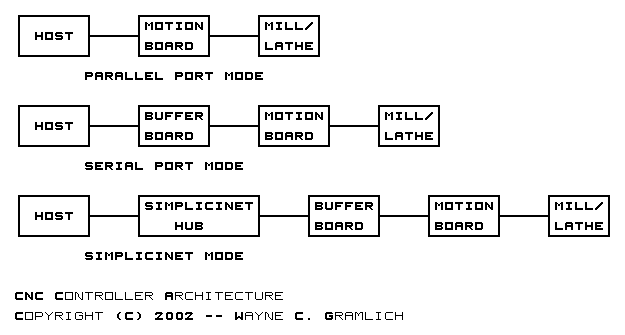
There are a total of three configurations:
-
Parallel Port Mode
-
In parallel port mode, the motion board is
directly connected to the parallel port of
the host processor.
-
Serial Port Mode
-
In serial port mode, the buffer board is
connected to the host processor via a
high speed serial port and the motion
board is connected to the buffer board.
-
SimpliciNet Mode
-
In SimpliciNet mode, the buffer board
is connected to the high speed serial
port of the host processor via a
SimpliciNet hub
[SimpliciNet]
and the motion board is connected to
the buffer board as before.
These three configurations are shown diagramatically
below:
Before I get into the design issues of the motion
control board, I would like to point out that the
various revisions of the board are kept in a
separate
motion control directory.
The motion board takes standard step
and direction signals for up to 4 axes
and generates the corresponding coil
excitations for up to 4 stepper motors.
The motion board is designed around the L298
[L298] dual H-bridge
which provides up to 2 amperes of current
per coil with a maximum voltage of 46 volts
(actually only 40 volts due to my choice of
Schottky diode.)
The motion board is designed to operate
with the Enhanced Motion Control
[EMC] software.
Thus, the pin-outs on the parallel port
are compatible with EMC pinouts.
The pinouts are copied from a table put
together by Lawrence Glaister
[Glaister]
The differences is that I added another
axis called A and I have changed the
way that limits are dealt with:
| Pin |
EMC Signal |
Motion Board |
| Number |
Name |
Direction |
| 1 |
/C0 |
Out |
n/a |
n/a |
| 2 |
D0 |
Out |
X Direction |
X Direction |
| 3 |
D1 |
Out |
X Step |
X Step |
| 4 |
D2 |
Out |
Y Direction |
Y Direction |
| 5 |
D3 |
Out |
Y Step |
Y Step |
| 6 |
D4 |
Out |
Z Step |
Z Step |
| 7 |
D5 |
Out |
Z Step |
Z Direction |
| 8 |
D6 |
Out |
n/a |
A Step |
| 9 |
D7 |
Out |
n/a |
A Direction |
| 10 |
S6 |
In |
Probe (Polarity=1) |
Probe (Polarity=1) |
| 11 |
/S7 |
In |
Probe (Polarity=0) |
Probe (Polarity=0) |
| 12 |
S5 |
In |
X, Y, Z Home (Polarity=1) |
A, X, Y, Z Home (Polarity=1) |
| 13 |
S4 |
In |
X, Y, Z Limit- (Polarity=1) |
Ground |
| 14 |
C1 |
Out |
n/a |
n/a |
| 15 |
S3 |
In |
X, Y, Z Limit+ (Polarity=1) |
Ground |
| 16 |
C2 |
Out |
n/a |
n/a |
| 17 |
/C3 |
Out |
n/a |
n/a |
| 18-25 |
Ground |
Ground |
Ground |
Ground |
Typically, systems that use L298's also use
the corresponding L297 [L297].
The L297 is a stepper motor controller chip
that provides a step and direction interface
to drive the L298 H-bridge. There are two
issues with the L297:
-
It is unclear whether the L297 is still
in full production. The supplies seem
to be getting more and more scarce.
-
Correspondingly, the cost of the L297
seems fairly high considering its
fairly modest functionality.
My preference is to use a less expensive
Microchip microcontroller that is dedicated
to do essentially the same task as the L297.
The
revision A uses a PIC16C505 and the
revision B uses a PIC16F628. (The
revision A design had a serious design
flaw.)
In order download the programs into the
microcontroller, a small PIC programmer is
placed in one corner of the board. (I hope
I have the board space!)
There are three kinds of wave tables that
make sense and these are listed below:
-
Wave Stepping
-
In wave stepping, only one coil is active
at a time. First coil A is tuned on,
then coil B, then coil A in the opposite
direction, then coil B in the opposite
direction and repeat. This mode consumes
the least amount of power and provides
the lowest amount of torque.
-
Full Stepping
-
In full stepping, the two coils are always
turned on. First A and B are forward,
then A in inverted, B is inverted, A
is pushed forward and repeat. The mode
consumes the most power and provides the
most torque (i.e. double the torque of
wave stepping.)
-
Half Stepping
-
In half stepping, the coils are turned
on in a sequence that provides twice as
many steps as the previous two modes.
With half stepping first one coil is
turned on, then two, then back to one
then back to two. It is basically
interleaved wave and full stepping.
All three tables are listed below:
| Wave Stepping |
| Phase |
CoilA+ |
CoilB+ |
CoilA- |
CoilB- |
| 0 |
1 |
0 |
0 |
0 |
| 1 |
0 |
1 |
0 |
0 |
| 2 |
0 |
0 |
1 |
0 |
| 3 |
0 |
0 |
0 |
1 |
| Full Stepping |
| Phase |
CoilA+ |
CoilB+ |
CoilA- |
CoilB- |
| 0 |
1 |
1 |
0 |
0 |
| 1 |
0 |
1 |
1 |
0 |
| 2 |
0 |
0 |
1 |
1 |
| 3 |
1 |
0 |
0 |
1 |
| Half Stepping |
| Phase |
CoilA+ |
CoilB+ |
CoilA- |
CoilB- |
| 0 |
1 |
0 |
0 |
0 |
| 1 |
1 |
1 |
0 |
0 |
| 2 |
0 |
1 |
0 |
0 |
| 3 |
0 |
1 |
1 |
0 |
| 4 |
0 |
0 |
1 |
0 |
| 5 |
0 |
0 |
1 |
1 |
| 6 |
0 |
0 |
0 |
1 |
| 7 |
1 |
0 |
0 |
1 |
It turns out that the microcontroller only
implements the half stepping wave table.
The other two tables can be `synthesized'
by simply using all even phase numbers
(Wave Table) or all odd phase numbers
(Full Stepping).
To simplify cabling, the motion board uses a
DB25 cable to connect from the controller to
the stepper motors, limit/home switches, and
linear/shaft encoders. Since DB25 cables
are primarily designed to support signal
transmission rather than power transmission,
a total of 8 wires are dedicated for each
coil (4 for each side.) Thus, a total of
16 wires are used for stepper motor power.
The remaining 9 wires (= 25 - 16) are used
for limit/home switch detection and
linear/shaft encoders. The pin-outs are
listed below:
| Pin |
| Number |
Name |
Direction |
| 1 |
Home |
In |
| 2 |
EncoderPhase1+ |
In |
| 3 |
CoilB+1 |
Power |
| 4 |
CoilB+2 |
Power |
| 5 |
CoilB-1 |
Power |
| 6 |
CoilB-2 |
Power |
| 7 |
Limit+ |
Current Loop |
| 8 |
CoilA+1 |
Power |
| 9 |
CoilA+2 |
Power |
| 10 |
CoilA-1 |
Power |
| 11 |
CoilA-2 |
Power |
| 12 |
+5V |
Power |
| 13 |
EncoderPhase2+ |
In |
| 14 |
Ground1 |
Ground |
| 15 |
EncoderPhase1- |
In |
| 16 |
CoilB+3 |
Power |
| 17 |
CoilB+4 |
Power |
| 18 |
CoilB-3 |
Power |
| 19 |
CoilB-4 |
Power |
| 20 |
Limit- |
Current Loop |
| 21 |
CoilA+3 |
Power |
| 22 |
CoilA+4 |
Power |
| 23 |
CoilA-3 |
Power |
| 24 |
CoilA-4 |
Power |
| 25 |
EncoderPhase2- |
In |
| 26 |
Ground2 |
Ground |
When it comes to limit switches there are two basic
strategies:
-
Advisory Strategy
-
The adviosory strategy is that a limit
switch event is forwarded to the software
that in turn responds by shutting the
whole machine down in a fairly graceful
fashion.
-
Depower Strategy
-
The depower strategy is that the moment
that a limit switch event occurs, power
is immediately removed from all drive
motors and spindle motors.
It should be noted that these two strategies are
not mutually exclusive. One set of limit switches
can be set up for an advisory strategy and another
set of limit switches can be set up for the depower
strategy. If the software does not get the machine
shut down when the advisory limit switch is triggered,
the depower limit switch can depower the whole
system.
EMC [EMC] implements the advisory
strategy for limit switches. I am real nervous about
relying exclusively on the advisory strategy because
it relies on some fairly complex software doing the
"right thing" in all circumstances. The next option
is the "let's support both". There are two problems
with supporting both -- first, the it takes up even
more cable conductors and board space, and second it
allows people to be sloppy about the depower switches,
since `after all they are really only there if the
first set does not work.' Ultimately, I decided that
I only wanted to support the immediate depower strategy.
This causes all limit switches to be hooked in series
with a current passing through all of them to a relay
that supplies drive and spindle motor power. If any
cable gets damaged, unplugged, or a limit switch is
triggered, the current throught the relay is cut off
and the whole system powers down. This is real simple
and real safe.
What this means for EMC is that the Limit- and
Limit+ are tied to ground. Thus, as far as
EMC is concerned, it will never get a limit
switch advisory signal.
The DB25 connector used to connect to each axis
has 4 wires set aside for transimitting standard
quadrature signals from linear/shaft encoders.
The two quadrature phases are sent using RS-422
levels to ensure that there is high noise rejectcion
due from the power pulses being sent down the
the same 25-wire cable.
The
Revision A and
Revision B versions of the
motion board are based on the EMC-style
advisory limit switches. The
Revision C is based on depower style of
limit switch.
The rest of the information about the motion
control board is kept in the
motion control directory.
{The Buffer Board is still in the early design phase.}
This section discusses the theory behind the buffer
board.
In the process of using CNC to manufacture a part,
a series of software and hardware tools are used to
transform the idea into physical reality. In theory,
a CAD system is used to design the part and a CAM
system is used to take the design and produce the
tool path that is used to manufacture the part.
The tool path is most typically represented as a file
in RS-274 format, which is also known as `G-codes'.
In the process of generating the toolpath, the CAM
system has to take into account the various
characteristics of the CNC equipment being used
and the properties of the material being machined.
Thus, the toolpath for an identical part being
machined on a CNC Bridgeport knee mill might be
quite a bit different from the toolpath on a CNC
Sherline table top mill. The additional power
available in the Bridgeport spindle, the increased
tool rigidity and increased X, Y, and Z axis power
allow the Bridgeport to take significantly deeper
and faster cuts over its smaller Sherline cousin.
None the less, the resulting part can be, for
all intents and purposes, identical.
Once the toolpath has been generated it is up to
CNC controller to take that G code and translate
it into a series of precisely timed and coordinated
moves on the CNC machine. The coordinate space
of G codes is in either English or Metric units
measured to fractions of inch or fractions of
a millimeter. The coordinate space of the CNC
machine is integral units where each unit is
typically something small like .00025 of an inch
or some such. The CNC controller is responsible
for converting from the G code coordinate space
to the machine coordinate space.
From an abstract point of view, the CNC controller
takes the G-Code and reduces it to a sequence of
timed events of the base form `at time t, move
to position (x, y, z)'. Combining the time time
into a four-tuple results in a sequence of
4-tuples (t, x, y, z). (This example is for a 3
axis machine, each additional axis would lengthen
the tuple appropriately.)
Historically the conversion of G codes to a sequence
of timed events has been done by a single dedicated
processor. However, it is possible separate the
generation of the timed event sequence from the
actual processing of the events on the CNC machine.
The timed event sequence can be generated on any
general purpose computer and the processing of the
timed events can be performed by specialized hardware
that can carefully emit the control signals at
exactly the right time. I call this specialized
hardware a buffer, since it is responsible for
storing up a bunch of motion commands and emitting
them at just the right rate.
The question arises, how big does the buffer need
to be? At one extreme the buffer can be large
enough to store all of the tuples before even
the first one is executed. At the other extreme,
the buffer can be of size zero and we are back
to the situation where the processor that is
computing the tuples is responsible for the timing
as well. In the middle, there is a buffer that
is large enough to ensure that the machine never
runs out of timed events (i.e. buffer under run) and
is not prohibitively expensive.
Before the question of how big the buffer is
can be answered, it is necessary to get a handle
on how much bandwidth is required between the
G-code to timed event converter and the buffer
board.
The timed event stream is amenable to a large
amount of compression. The first thing to note
is that the times are monotonically increasing.
The next thing to note is that when the machine
is moving from machine coordinate X1
to Xn it must traverse all intermediate
coordinates. Thus, delta encoding will result
in substantial bandwidth savings. Thus, the
sequence (123657, 23459, 5432, 98623),
(123663, 23460, 5432, 98623),
(123668, 23460, 5431, 98623) can be encoded
as an initial value of (123657, 23459, 5432, 98623)
followed by delta values of (6, 1, 0, 0) and
(5, 0, -1, 0). Note, that the first element
must always be positive and the remaining
elements must be -1, 0, or 1.
The rate at which these event tuples are
processed depends upon the maximum stepping
rate of the machine in question. If each
machine axis is capable of being ramped up to
100,000 steps per second, there are potentially
up to 3 × 100,000 event tuples per second
that need to be processed, since the steps
may not be occuring in sequence. If we set
aside 6 bits for the time delta, and 2 bits
for the each axis delta, that results in 10
bits per delta or 3 × 100,000 ×
10, or 3Mbps. While, this is not a small
number, it is nice to have an upper bound
on the required bandwidth.
Are there additional ways of compressing the
information? Certainly. The way that looks
the most promising to me is to break the
event stream up on a per axis basis. By noting
that the axis motor is limited by its maximum
acceleration and deceleration, it should be
possible to come up with a much more compact
representation of the axis event stream. For
example, if the motor is running at a constant
velocitiy, a simple run code compression can
be used. For run code compression, a sequence
of evently spaced events can be replaced by just
counting how many equally space events there are.
Similarly, when the motor speed is being changed,
a code that describes the amount of acceleration
(or deceleration) can compress a whole bunch of
motor events. Once the per axis event streams
have been computed, they can be mixed back together
to form a single unified stream.
One possible command stream might look as follows:
-
Axis Id (3-bits)
-
For a 3 or 4 axis machine, only 2-bits
are needed. For a full 6 axis machine
3 bits are needed.
-
Acceleration/Deceleration (5-bits)
-
This is a 5-bit signed two's complement
number. It is zero when the motor is
running at a constant speed. It is negative
to decelerate and positive to accelerate.
-
Event Count (8-bits)
-
The repeat count specifies how many event
counts are covered by this command.
The time is implied as the end of the previous
command for this axis. For example to deccelerate
the X axis from one step every 100 µS,
to one step every 200 µS, a command of
(0, -2, 100) would do the trick. To keep
the motor going for 1000 steps, 4 commands of
(0, 0, 250) would do the trick.
Yes, there are lots of details to work out.
However, I am quite hopeful that the bandwidth
required to keep a CNC machine happy can be
well under the 3Mbps mentioned above, preferably
under the 115Kbps that most asynchronous serial
lines need.
The next step is to get some more solid numbers.
In order to do this, my plan is to take the
Enhanced Machine Controller [EMC]
and modify it to produce an timed event stream.
After that, I intend to experiment a little to
figure out what kinds of compression work well
on the stream.
This is still pretty rough!
The buffer board has the following features:
-
The buffer board microcontroller is a
PIC16F877. This microcontroller has an
on board UART and 30+ I/O lines.
-
The PIC16F877 can be programmed in LVP mode.
The PIC505's can be programmed using an
on board PIC programmer.
-
Communication with the host processor occurs
either through an RS-232 connection or a
SimpliciNet connection.
-
The buffer board basically can independently
control 4 axes via the the standard parallel
port connector with standard EMC pinouts.
-
The limit and home signals for all axes are
individually accessable.
-
The current for each stepper motor can be
individually set, thereby providing the
ability to perform microstepping.
-
There is support for one linear or shaft
encoder with quadrature encoding on each
axis.
-
The spindle motor can be independently
controlled in both speed and direction.
The motor speed can be measured using
a tachometer signal.
-
The ability to read a few of the more
common SPC gage protocols is supported.
-
The buffer board has a second parallel port
output to support the second EMC parallel
port option. This second parallel port
provides additional controls above the
standard second EMC parallel port options:
-
A signal is provided for powering up and
down the stepper motor power supply.
-
A panic stop button is supported.
-
A sonic alarm is provided to get attention
that something is wrong.
-
The ability to control a tool changer.
This includes sensing tool home and the
the presense of tools.
-
The ability to control a power drawbar.
-
The ability to read an analog voltage for
EDM strength is provided. This can be used
to control EDM feedrate.
The following features did not make the cut:
-
Control Panel
-
A control panel allows the user to manually
control the CNC machine. This is best done
with a separate board that connects via
a SimpliciNet connection.
-
Power supply
-
The power supply should just be purchased
separately.
As usual, the shaft encoders use a dedicated PIC
to keep track of the position...
Before I get into the buffer board design, I would
like to point out that the individual revisions of
the buffer board are kept in a
buffer board revision directory..
{Remaining design issues go here.}
I have received useful feed back from `Ballendo'
and Doug Fortune about mistakes in this document
that I have attempted to correct. In addition,
I have found the CAD_CAM_EDM_DRO group at
Yahooo [E] to
be extremely informative. Other useful tidbits
of information have been mined from the
rec.crafts.metalworking newsgroup.
-
[CAD_CAM_EDM_DRO]
-
CAD_CAM_EDM_DRO group at
Yahoo. URL:
http://groups.yahoo.com/group/CAD_CAM_EDM_DRO/
-
[Camtronics]
-
Frames URL:
http://www.seanet.com/~dmauch/.
Non-Frames URL:
http://www.seanet.com/~dmauch/site_map.htm.
-
[EMC]
-
Enhanced Machine Controller
URL
http://www.isd.mel.nist.gov/projects/emc/ developed
by the
National Institute of Standards and Technology
The source code is available from
SourceForge at URL:
http://www.sourceforge.net/projects/emc/.
-
[CNCKits]
-
Frames URL:
http://cnckits.com/
Non-frames URL:
http://web.cuug.ab.ca/~fortuned/cnckits/
-
[Geckodrive]
-
URL:
http://www.geckodrive.com/.
-
[Glaister]
-
Lawrence Glaister's CNC pages. Main URL:
http://members.shaw.ca/cncstuff/
Bridge circuits URL:
http://members.shaw.ca/cncstuff/bridges.html.
EMC parallel port pinouts URL:
http://members.shaw.ca/cncstuff/emcio.html
-
[L297]
-
Stepper Motor Controllers by
ST.
-
[L298]
-
Dual Full Bridge Driver by
ST.
-
[LS7266R1]
-
The LS72661R1 is a 2 channel quadrature encoder
chip from
LSI Computer Systems Inc.
-
[Mauch1999]
-
Three-Axis Chopper, Step Motor Controller
for Computer Numerical Control (CNC)
Applications, Part 2 by Dan Mauch
June 1999 (pp. 6-8) issue of
Nuts and Volts magazine (Vol. 20, No. 6).
Part 2 of a 4 part series in the
May through
August issues.
-
[PIC16C505]
-
14-pin 8-bit CMOS Microcontroller by
MicroChip.
-
[RTLinux]
-
URL:
http://www.fsmlabs.com/.
-
[Rutex900]
-
Rutex
RT900 Motion Control IC.
-
[SimpliciNet]
-
SimpliciNet URL:
http://web.gramlich.net/projects/simplicinet/index.html.
-
[Wedemeyer1999]
-
Author: Hans Wedemeyer.
Bi-Polar Motor Driver.
-
URL:
http://hans-w.com/cnc.htm (about half
way down.) Image Only URL:
http://hans-w.com/9908-09A.gif.
This appendix contains some fairly free form
notes about CNC as I slowly start to figure
all this stuff out.
-
Mill Types
-
There appear to be two styles of
vertical mill -- a knee mill where
the spindle is kept rigid with
respect to the floor and the other
kind (name?) where the spindle is
moved veritcally in the Z axis.
Thus, the table for a knee mill
moves in the X, Y, and Z axes.
The other kind (name?) only moves
the table in the X and Y axises and
the spindle moves in the Z axis.
Knee mills seem to be bigger, so
they have more Z axis travel. The
larger Z axis travel translates into
fewer hassles with getting tools into
and out of the spindle.
-
Backlash
-
Leadscrew backlash is the slop in the
system as the table pushes agains one
side of the lead screw of the other.
An ideal milling system has no backlash.
Unfortunately, real milling systems
can have a great deal of backlash.
There are at least four ways (probably
many more) of dealing with backlash:
-
Ball Screws
-
A ball screw is magical device that
has ball bearings that push against
both sides of the lead screw at the
same time. By properly grinding and
hardening the lead screw and ball
screw races, wear is greatly reduced.
In addition to having essentially no
backlash, ball screws have very little
friction as well. The only drawback
is that they cost a small fortune.
They are not really an option for a
table top mill right now.
-
SuperNuts
-
I'm not sure I have the terminology
right here. Apparently there are
nuts that can be placed on a lead
screw to take out all of the backlash.
I suspect that they are somethting as
simple as two threaded nuts with a
spring between them. I need to find
out more here.
-
Pre Loading
-
Anyhow, the concept is to apply a
constant force to one side of the lead
screw. There are several ways of
accomplishing this task -- weight
and pullys, springs, etc.
A less clunky looking solution is to
mount another nut on the lead screw
and put a stiff spring between the two.
Any way it is done greatly increases
the friction and leadscrew wear. The
good news is that the hobbyist lead screws are pretty
cheap, so for hobbyist use, it is probably
OK to shorten their lifetime. Another
drawback is that the cutting tool can
temporarily overcome the side load force
and cause surface imperfections. The
big down side for side loading is the
need for larger motors to overcome the
increased friction.
-
Compensation
-
The more common strategy is to compensate
for backlash in software. This works
pretty well as long as the tool is
being pushed against one side of the
lead screw. Whenever there is an
inflection point in tool cutting path
the software quickly steps to the other
surface of the lead screw. But while
this is happening the cutting bit is
free to flop around a little. Again
this results in a surface imperfection.
-
Coupling Nut
-
A coupling nut is a longer threaded nut
made out of plastic material that is
at least 3 times longer than the diameter
of the leadscrew. It is inexpensive,
does not appear to add much wear and
does not appear to add much drag while
significantly reducing backlash.
As near as I can tell, most systems compensate
for backlash and deal with any resulting problems.
I suspect that there is some serious issue with
the side loading solution that I do not understand,
because I do not know of anybody that uses it.
There is an additional issue of uneven wear
on the lead screw. Since most travel occurs
in the middle of the lead screw, that is where
the most slop is introduced. For small machines,
the lead screw is cheap and should be replaced
when it gets unevently worn.
-
Encoders
-
An encoder is used to measures where the
X, Y, and Z axes are.
There are two kinds:
-
Linear encoder
-
The linear encoderss are attached to
the table proper and measure the exact
X, Y, and Z location in relation to
the spindle. The less expensive
encoders seem to be clocking in at
.001" to .00025". The linear system
can compensate for thermal expansion
and contraction in the table.
-
Shaft encoder
-
A shaft encoder sits on the lead
screw and measure thes amount of
lead screw rotation. A shaft encoder
can be be accurate up to 2048*4
counts per rotation. Given that
a lead screw might be 20 TPI (threads
per inch) this results in a theoretical
resolution of .0000061035". The big
disadvantage of shaft encoders is that
they only measure the lead screw
position, excluding any backlash.
Backlash will eat up the accuracy of
a shaft encoder.
-
SPC
-
SPC stands for Statistical Process Control.
The concept is to measure your parts and
notice when they are getting out of kilter
and replace the dull tool that is causing
the problem before they get too far out of
kilter. For the small hobbyist kind of guy
what this really means is that your
measurement tools have a digital output
that can be fed into a computer to be used.
The bad news is that there is not that much
standardization on the connectors, wires,
voltages, and protocol. Sigh, that means a
lot of custom adaptors.
There are two kinds of drive sytems:
-
Stepper Motor
-
A stepper motor is a motor without
a commutator that is controlled by
selectively turning coils on and
off. Stepper motors cost more per
lbf (pounds force) than DC motors.
-
Servo Motor
-
A servo motor is a standard DC motor
coupled with some feedback circuitry
to detect position errors an correct
them. DC motors cost less per lbf
(pounds force) than stepper motors.
There are pros and cons between using stepper
motors and servo motors to control everything.
Right now stepper motors seem to be holding the
low end of the market and servos are holding
the high end. For the same amount of torque,
stepper motors seem to be more expensive. For
a large machine, a large stepper motor will cost
a lot. Stepper motors can be run open loop.
Servo motors always have to have some sort of
feedback in the system. In theory, when a
stepper motor is not moving, it is being held
with a very large torque. When a servo motor
is not moving, its torque may be bouncing on
and off a little as the tool is pushed ever
slightly off its mark. On some servos systems
there is a certain roughness that results.
Other people claim this is really just an
improperly tuned servo system (and I tend to
agree.) The smaller mills seem to be standardizing
on NEMA 23 mounts for stepper motors.
Stepper motors coils are driven in cyclical
fashion. There are four ways to drive a stepper
motor:
-
4 steps per cycle, one coil active (wave)
-
This cycle is N, E, S, W and repeats.
-
8 steps per cycle (half stepping)
-
This cycle is N, NE, E, SE, W, SW, W, NW
and repeats. The NE, SE, SW, and NW
cylces have two coils simultaneously
active thereby doubling the torque
on those steps.
-
4 steps per cycle, two coils active (full stepping)
-
This cycle is NE, SE, SW, NW and repeats.
This cycle has twice the torque of the
first N, E, S, W cycle. Given that
stepper motors cost a lot for a given
torque, any technique that will double
the torque is pretty important.
-
Microstepping
-
With microstepping the current is varied
through the currently active two coils
to obtain an additional level of positioning
accuracy.
If too much current flows through a stepper motor
coil it will over heat and cause a motor failure.
There are four basic solutions.
-
Constant Voltage
-
The constant voltage system is the simplest
and slowest. If the stepper motor is rated
for N volts, no more than N volts is every
supplied to the coil. This is simple and
results in the lowest performance.
-
Series Resistor
-
A resistor can be placed in series with the
coil. A higher voltage is applied to the
coil. The series resistor is picked to
limit the current through the coil using
Ohms law (V = I * R). Essentially when
the coil is fully on, the voltage drop
across the resistor is same as the constant
voltage. When a coil is first activated,
the current can ramp up quickly because there
is no voltage drop across the resistor.
-
Chopper stablized
-
Chopper stablized is the next one up. A
higher voltage is supplied. The voltage
is turned on and off depending upon whether
the current is too high or not. The current
is sensed using a small current sensing
resistor near ground.
-
Variable voltage
-
I haven't seen this one done yet, but it
is pretty straight forward. The current
is measured and voltage is increased or
decreased appropriately. The voltage can
be supplied using a switching supply so
that it is not a power hog.
Right now the middle two seem to be the most used
solutions. Frankly, the variable voltage solution
should be given a try.
There are two kinds of stepper motors:
-
Bipolar
-
A bipolar stepper motor has two
coils. The each coil can be individually
activated. Call one coil the north
south coil and the other the East West
coil. This gives 8 possible activation
combinations - N, NE, E, SE, W, SW, W, and
NW. A bipolar stepper motor as a total
of four wires -- 2 wires for the north
south coil and the 2 wires for the east
west coil. Bipolar stepper motor coils
need to be driven with an H bridge to
be able to control which direction the
current flows through the coil.
-
Unipolar
-
A unipolar stepper motor is one that
that has two coils, but the each coil
has a center tap. Furthermore, the
windings on one side of the centertap
are clockwise and on the other side
they are counter clockwise. What this
means is that current from the centertap
to one side will activate the coil in
one direction (say north) and current
from the centertap to the othe size will
activate the coil in the opposite direction
(in this case south.) A unipolar stepper
motor can connect the centertap to a
positive voltage and use one transitor
on either end of the coil to control
energization direction. Thus, a unipolar
stepper motor does not need an H-bridge
to control current direction. In general,
a unipolar stepper motor of a given mass
has half the torque of a similar mass
bipolar stepper motor. This is because
only half the coil is active at a time.
Interestingly enough, it appears to be possible to
use unipolar stepping motors in a bipolar mode.
The only catch is you have to cut the current in
half because there are twice as many turns active
at a time. Very interesting.
There are at least three ways of connecting the
motor to the lead screws:
-
Direct drive
-
Direct drive hooks the motor shaft
directly to the lead screw shaft.
Done properly, there is no additional
backlash introduced.
-
Belt drive
-
The motor shaft is attached to the
lead screw shaft with a drive belt.
A reduction ratio can be added to
slow down a faster DC motor and
get correspondingly more torque.
There is an opportunity to add some
backlash into the system with belt
drive.
-
Gear Drive
-
A gear drive uses a gear train to
connect the motor shaft to the
lead screw shaft. One simple
strategy is to use a worm gear.
Like belt drives, backlash can
be added to the system.
Thermal expanstion and contraction rears its
ugly head in metalworking. As the temperature
changes, the metal part, the cutting tool,
and the machine tool expand and contract as
the temperatur changes. If the cutting tool
overheats, it will frequently be rendered
unusable. Whenever you are working on part
that need that level of accuracy, trying to
keep the temperatures constant starts to matter.
The big professional machining centers actually
will refrigerate the bearings, motors, etc. to
keep everything at a constant temperature. The
poor mans equivalent is to run everything in an
air conditioned shop; not as good, but not as
expensive either.
There seem to be at lest five kinds of cooling:
-
None
-
Basically, everything is ether run slow
so heat does not build up; or more
counter intuitively, things get done fast
so that the chips that are thrown out
carry most of the heat away.
-
Flood Cooling
-
A flood of cooling fluid is drenched over
the work piece. Everything is sprayed all
over the place. This is very effective
and quite messy. You need to have a drip
pan to collect the run off, a filter to
keep the chips out the pump, a pump to
pump it up again, etc. Lastly, the fluid
can mess up some the optical encoders out
there.
-
Mist Cooling
-
A fine mist of coolant is sprayed onto the
piece. Seems to work fine. There are
lots of complains about the mist getting
all over the shop and into people's lungs.
Yech.
-
Drip Cooling
-
A trickle of cooling fluid is dripped onto
the piece. There is much less splatter.
-
Hybrid Mist/Drip
-
There seems to be hybrid between mist and
drip whereby somebody has a fine mist wand
that is sprayed directly onto the part.
The lung irration complaints are way down.
-
Vortec Cooling
-
Vortec cooling uses swirling presurized
air and separates it into hot air and
cool air. The cool air is blown onto
the part. It is quite loud.
Lastly, the various liquid coolant systems can mess
up encoders real fast. Care needs to be taken to
keep the encoders sealed gains coolant. It tends
to be easier to seal a rotary encoder than a linear
encoder.
Where does that leave us? The first issue to
deal with is backlash control. For table top
systems, ball screws are out because they are
too expensive. That leaves conpensation vs.
preloading. With preloading friction is way up,
so the motors need to be correspondingly larger
to overcome the friction. However, this means
that the system can be run open loop with no
encoders. If encoders are added, they can be
the rotoary kind and sealed against any coolant.
If there is going to be no preloading, then
backlash compensation is a necessity. Open
loop backlash compensaton only works up to a
point. Linear DRO's will allow the system to
compensate out any backlash. They also
compensate out lead screw wear. The linear
DRO's need to be sealed agains any coolant.
For small hobby mills, both stepper and servo
systems will work. For now, it is probably better
to go with stepper motors in NEMA23 frames since
that seems to be the better supported solution.
It would be tempting at some point in the future
to try out an inexpensive gear drive motor directly
coupled to the shaft with an inexpensive shaft
DRO.
For stepper motors, bipolar motors with either
chopper drive or variable voltage seems to be
the way to go. Unipolars can be used in bipolar
mode.
Copyright (c) 2001-2002 by
Wayne C. Gramlich.
All rights reserved.