This is the Revision A version of the Out10 RoboBrick. The status of this project is that it has been replaced by the InOut10 RoboBrick.
This document is also available in PDF format.
The Out10 RoboBrick provides the ability to output 10 bits of data.
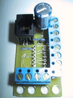
A picture of an Out10-A RoboBrick is shown below:The Out10 RoboBrick supports the standard shared commands in addition to the following commands:
Command Send/Receive Byte Value Discussion 7 6 5 4 3 2 1 0 Write Lower Send 0 0 0 f g h i j Write fghij out to the lower 5 bits. Write Upper Send 0 0 1 a b c d e Write abcde out to the upper 5 bits. Bit Clear Send 0 1 0 0 b b b b Turn bit bbbb off.
MSB (bbbb=1010) LSB (bbbb=0000)Bit Set Send 0 1 0 1 b b b b Turn bit bbbb on. Bit Toggle Send 0 1 1 0 b b b b Toggle bit bbbb. Bit Read Send 0 1 1 1 b b b b Read status of bit bbbb. Receive 0 0 0 0 0 0 0 b Bit state is b. Read All Send 1 0 0 0 0 0 0 0 Read all ten bits. Receive 0 0 0 a b c d e Upper five bits abcde Receive 0 0 0 f g h i j Lower five bits fghij Read Lower Send 1 0 0 0 0 0 0 1 Read lower five bits. Receive 0 0 0 f g h i j Lower five bits are fghij Read Upper Send 1 0 0 0 0 0 1 0 Read upper five bits. Receive 0 0 0 a b c d e Upper five bits are abcde Increment Bits Send 1 0 0 1 b b b b Increment bits starting at bit bbbb Decrement Bits Send 1 0 1 0 b b b b Decrement bits starting at bit bbbb Shared Commands Send 1 1 1 1 1 a b c Send shared command abc to RoboBrick.
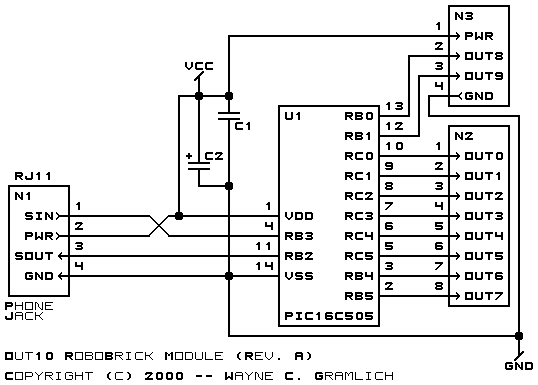
The hardware consists of a circuit schematic and a printed circuit board.
The schematic for the Out10 RoboBrick is shown below:
The parts list kept in a separate file -- out10.ptl.
The printed circuit files are listed below:
The Out10 software is available as one of:
The Out10 test suite is available as one of:
The following issues came up: