This is the specification portion of the RoboBricks Projects. It is currently work in progress.
There are three components to the RoboBrick specifications -- the software protocol, electrical protocol, and the mechanical connector specification.
The RoboBrick protocol is very simple. The controlling processor sends out one or more command bytes and the selected Robobrick responds with one or more response bytes. The RoboBrick protocol is asynchronous serial in 8N1 format (i.e. 1 start bit, 8 data bits, no parity, and 1 stop bit.) The protocol speed is at 2400 baud.
All of the slave RoboBricks share some common commands to help with glitches, RoboBrick identication, and clock drift management. These are discussed briefly below:
The shared commands are summarized textually below:
The shared command protocol is defined in the table below:
Shared RoboBrick Commands Command Bit Number Send/Receive Description 7 6 5 4 3 2 1 0 Glitch 1 1 1 1 1 1 1 1 Send Glitch Command Glitch Read 1 1 1 1 1 1 1 0 Send Glitch Read Command g g g g g g g g Receive Returns 8-bit gggggggg glitch counter value ID Reset 1 1 1 1 1 1 0 1 Send ID Reset Command ID Next 1 1 1 1 1 1 0 0 Send ID Next Command i i i i i i i i Receive Returns next 8-bit iiiiiiii identification byte value Clock Pulse 1 1 1 1 1 0 1 1 Send Clock Pulse Command 0 0 0 0 0 0 0 0 Receive Returns a null byte that can be timed for clock drift Clock Read 1 1 1 1 1 0 1 0 Send Clock Read Command c c c c c c c c Receive Returns the 8-bit cccccccc clock adjust register value Clock Increment 1 1 1 1 1 0 0 1 Send Clock Increment Command Clock Decrement 1 1 1 1 1 0 0 0 Send Clock Decrement Command
The identification bytes in each RoboBrick are arranged as follows:
Offset Name Description 0 RBMajor Major Version Number for identification stream (currently 1) 1 RBMinor Minor Version Number for identification stream (currently 0) 2 BrickID BrickID for common Bricks (see table below) 3 BrickRev Brick Revision (0=A, 1=B, 2=C, 3=D, 4=E 5=F, 6=G 7=H, etc.) 4 BrickFlags 8 RoboBrick Specific Flags 5 Reserved0 (use 0) Reserved for future use 6 Reserved1 (use 0) Reserved for future use 7 Reserved2 (use 0) Reserved for future use 8-23 UID0-15 128-bit Unique Identifier (Randomly Generated) 24 NameLength RoboBrick Name Length Next NameLength Bytes BrickName Name of RoboBrick in ASCII Next Byte VendorLength Vendor Name Length Next VendorLength Bytes VendorName Vendor Name in ASCII Next Byte OptionsLength Options Length (optional) Next OptionLength Bytes Options Option Bytes (optional)
The BrickFlags are currently defined as follows:
Bit BrickFlags Description 7 6 5 4 3 2 1 0 c c=1 => clock adjust supported i i=1 => interrupt protocol supported o o=1 => optional bytes follow vendor name b b=1 => Baud rate change is allowed
The RoboBricks are given for BrickID identifiers on a first come first serve basis. The following identifiers have already been allocated:
ID RoboBrick Name 0-7 Reserved for experimenters 8 LED4 (obsolete) 9 LED10 (obsolete) 10 In8 (obsolete) 11 BIROD2 (abandoned) 12 AnalogIn4 13 Out10 (obsolete) 14 Motor2 15 Servo4 16 Shaft2 17 Stepper1 18 Switch8 (obsolete) 19 Threshold4 (obsolete) 20 AIROD2 (abandoned) 21 Compass360 (obsolete) 22 Compass8 (obsolete) 23 InOut10 24 Laser1 25 Light4 26 Sonar1 (abandoned) 27 AIROD4 28 BIROD5 (abandoned) 29 SONARDT1 30 Bill Hubbard's RC4 31 IRProximity2 32 Digital8 33 DualMotor1Amp 34 IREdge4
Each brick is assigned a 128-bit random number.
The probability of two bricks being assigned the
same random number is 1/(2128) which is
a pretty small number. On Linux, the random numbers
can be read from /dev/random
(or /dev/urandom.)
At 2400 baud, it can take a while to poll several input RoboBricks to see if anything interesting has occured. Sometimes RoboBricks are sensing inputs that need a response that is faster than strict polling can provide. For example, bumper detectors. To support low latency, many RoboBricks support the RoboBrick Interrupt Protocol.
The RoboBrick Interrupt Protocol is very simple. Each RoboBrick that supports the protocol has two bits -- the interrupt pending bit and the interrupt enable bit. The interrupt pending bit is set by the RoboBrick when a prespecified user event has occured. The interrupt enable bit is set to allow the interrupt to occur.
The following steps occur when using interrupts:
Since many RoboBricks will implement the RoboBrick Interrupt Protocol, there are some common commands defined to support the protocol:
Command Send/
ReceiveByte Value Discussion 7 6 5 4 3 2 1 0 Read Interrupt Bits Send 1 1 1 0 1 1 1 1 Return the interrupt enable bit e and pending bit p. Receive 0 0 0 0 0 0 e p Set Interrupt Bits Send 1 1 1 1 0 0 e p Set interrupt enable bit to e and pending bit to p. Set Interrupt Pending Send 1 1 1 1 0 1 0 p Set interrupt pending bit to p. Set Interrupt Enable Send 1 1 1 1 0 1 1 e Set interrupt enable bit to e.
As of the version 1.1 of the RoboBricks protocol, the ability to change baud rate has been added. All RoboBrick modules start out communicating at 2400 baud using an 8N1 (1 start bit, 8 data bits, No parity, and 1 stop bit) asynchronous serial protocol. A RoboBrick indicates that it can support increases in its baud rate by seting bit 3 in the BrickFlags byte (5th byte = offset 4) of the RoboBrick identificiation string.
There are three RoboBrick baud rate control commands:
The available baud rates are in the table below:
Baud Rate Code Mask (binary) 2400 0 0000 0001 4800 1 0000 0010 9600 2 0000 0100 19200 3 0000 1000 38400 4 0001 0000 57600 5 0010 0000 115200 6 0100 0000 230400 7 1000 0000
The detailed commands are:
Command Send/
ReceiveByte Value Discussion 7 6 5 4 3 2 1 0 Read Available Baud Rates Send 1 1 1 0 1 1 1 0 Return the available baud rates as a mask abcdefg where a=230400, b=115200, ..., h=2400 Receive a b c d e f g h Read Current Baud Rate Send 1 1 1 0 1 1 0 1 Return the current baud rate as rrr where rrr=000 => 2400, rrr=001 => 4800, ..., rrr=111 => 230400 Receive 0 0 0 0 0 r r r Set New Baud Rate Send 1 1 1 0 1 1 0 0 Set the new baud rate to rrr where rrr=000 =>2400, rrr=001 => 4800, ... rrr=111 =>230400. The first two bytes are sent at the old baud rate. The next two bytes are sent/received at the new baud rate. If the RoboBrick does not receive the last byte correctly at the new baud rate, this command will fail and the baud rate will remain unchanged. Send 0 r r r 0 r r r Receive 0 1 0 1 0 1 0 1 Send 0 1 0 1 0 1 0 1
The Set New Baud Rate command is a little tricky and merits additional discussion. Changing baud rates is potentially risky. If the host attempts to change the baud rate, and the target RoboBrick sets the baud rate incorrectly, the host will no longer be able to successfully communicate with the RoboBrick. The only way to recover is to reset power to the RoboBrick to get it back to 2400 baud. For this reason, the command to set the new baud rate requires positive acknowledgement that the baud rate has changed. The first two bytes of the command are sent at the old baud rate, where the second byte specifies the desired new baud rate. The next two bytes of the command are performed at the new baud rate. If the host does not get a '0101 0101', the knows that something has gone wrong. If the RoboBrick does not get a '0101 0101' from the host, the RoboBrick knows that something has gone wrong. If anything goes wrong, the baud rate reverts back to the original value.
After the baud rate for a RoboBrick has been set, it probably makes sense to run the clock adjust algorithm to make sure the RoboBrick clock is as close as possible to the host clock.
The RoboBrick electrical protocol is based around a 4 wires using standard 5-pin straight headers with .100 inch between the pins. The 4 wires are:
The printed circuit boards use standard .100 straight male headers. These are usually purchased in lengths of 30-40 pins (e.g. Jameco 160881), and are snipped to a length of 5 pins. The cables are manufactured using 5 pin female cable headers with .100 centers (e.g. Jameco 163686).
The pin outs for master boards are:
The cables are wired straight through with pin 2 left unconnected (i.e. pin 1 to pin 1, pin 3 to pin 3, pin 4 to pin 4 and pin 5 to pin 5.) 22 AWG stranded wire must be used for the cable wires. There is no offical color code for the cable wires.
Pin 2 is used to polarize the cable. A male pin (Jameco 145357) is jammed into pin 2 and the male pin that sticks out is snipped off For a properly polarized cable and RoboBrick boards, it is not possible to plug the cable into the board either backwards or off by one. It is possible to plug a master to a master and a slave to slave, but no harm results.
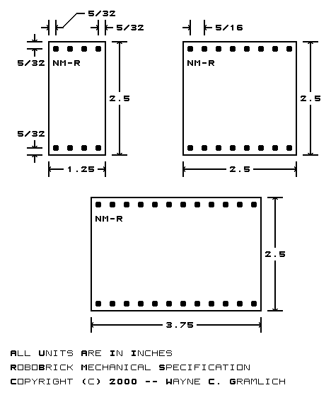
RoboBricks are compatible with the Lego®, MegaBloks®, and RokenBok® plastic toys. The standard pitch between studs on these toys is approximately 5/16 inches (or 4mm.) This means that a 4 by 4 square is 1.25 inches. The RoboBrick boards are always in units of 1.25 inch squares. All RoboBricks are 2.5 inches high by some multiple of 1.25 inches wide. Thus, the smallest RoboBrick is 1.25 by 2.5 inches, the next size up is 2.5 by 2.5, and the one after that is 2.5 by 3.75, etc.
The top and bottom of each RoboBrick has a row of holes that fit over the studs on plastic bricks. Thus, the holes are at least .195 inches in diameter. Since most RoboBrick printed circuit boards are double sided with plated through holes, the holes should probably be drilled with at least a .196 (#9) inch drill. For metric, a 4.9mm seems to work out reasonably well. The formula for determining the offset for stud N (where N starts at 0) is:
Offset = U/2 + N × Uwhere U is 5/16 of an inch. The expanded formula is:
Offset = .15625 + N × .31250The first 8 values for this formula are shown below:
After 8 entries, the numbers repeat offset by 2.5 inches.
Count Offset (in.) N×.05+/-offset 0 0.15625 3×.05+.00625 1 0.46875 9×.05+.01875 2 0.78125 16×.05-.01875 3 1.09375 22×.05-.00625 4 1.40625 28×.05+.00625 5 1.71875 34×.05+.01875 6 2.03125 41×.05-.01875 7 2.34375 47×.05-.00625 Repeats on 2.5 inch grid
Somewhere on each RoboBrick, must be name of the RoboBrick. The standard naming convention is `{name}-{revision}'. For example, 'Digital8-A', `DualMotor1Amp-B', etc. Please note that the revision corresponds to both hardware revision and the software revision inside the microcontroller.
A diagram of the mechanical specification is shown below: