This is the Revision A version of the Laser1 RoboBrick. The status of this project is that it has been replaced by the Revision B version.
This document is also available as a PDF document.
The Laser1 RoboBrick is a module that is designed to allow the use of a slightly modified laser pointer to detect passive refector beacons at a distance of approximately 10 meters (or about 32 feet for the metrically impaired.) It is meant to be used in conjunction with the LaserHead1 RoboBrick. It has a 3.1 volt power supply that can be turned on and off under program control to replace the batteries that come with the laser pointer. In addition, the Laser1 RoboBrick can send a pulses to a servo to cause it to slew back and forth under program control. In conjunction with 3 or more properly placed passive reflectors, the Laser1 RoboBrick can be used to triangulate a robot's position. We will not know how accurately until after it has been built and tested.
The basic idea behind this laser pointer system came from an article written by Jim Ubersetzig [Ubersitzig1999]. We are greatly indebted to Jim for figuring this system out in the first place and for E-mail support as we asked some follow on questions. The equations for doing triangualation can be found in a paper by Clare McGillem and Theodore Rappaport [McGillem1989]. A more recent on-line derivation of the formulas can be found in a paper by Richard Vannoy [Vannoy2001]. There is another paper by M. Bertke and L. Gurvits [Bertke1994] that explains how to deal with more than three beacons; alas, the math is quite a bit over my head. It should be mentioned that the McGillem and Gurvits papers were found by scanning the bibliography of the fairly comprehensive treatment of robot navigation by Borenstein, Everett, and Feng [Borenstein1996].
The initial software for the Laser1 RoboBrick will only be responsible for measuring the angles between the beacons and the robot proper. The next software/hardware reversion should be able to compute the (x, y) position of the robot, given the (x, y) positions of the beacons. The reason for the currently reduced functionality is because the floating point math libraries occupy more than the 2K of available code space on PIC16F628; indeed, all of the code appears to occupy a significant fraction of the 8K of code space available in a PIC16F876.
The current design requires a servo that has been modified for continuous rotation [AcronameServo, SandbergServo, Buse2000]. This allows the LaserHead1 to sweep a full 360 degrees. An additional sensor is used to detect each time the LaserHead1 sweeps past a known location.
Since the Laser1 uses a PIC16F628 with a 16 bit Timer1 module and the PWM/Capture/Compare module, it is capable of resolving the time between the beacon reflection returns to the instruction rate of 5 MHz. Since it takes our current laser head 2-3 seconds to slew 360 degrees, we need a counter resolution of 3×5×106 = 15 million. Since 15 million is greater than 64 thousand, a 24-bit counter is needed.
{to be continued...}
The BIROD2 RoboBrick supports both the standard shared commands and the shared interrupt commands in addition to the following commands:
Command Send/
ReceiveByte Value Discussion 7 6 5 4 3 2 1 0 Set Laser Enable Send 0 0 0 0 0 0 0 z Set laser enable bit to z Read Laser Send 0 0 0 0 0 0 1 0 Read and return the sweeping bit s, high bit h, low bit l, and laser bit z, and capture count nnnn. Receive s h l z n n n n Disable Servo Send 0 0 0 0 0 1 0 0 Disable servo Enable Servo Low Send 0 0 0 0 0 1 0 1 Enable Servo Low Enable Servo High Send 0 0 0 0 0 1 1 0 Enable Servo High Sweep Send 0 0 0 0 0 1 1 1 Sweep Set Servo Low Send 0 0 0 0 1 0 0 0 Set servo low register to llllllll Send l l l l l l l l Set Servo High Send 0 0 0 0 1 0 0 1 Set servo high register to hhhhhhhh Send h h h h h h h h Read Servo Low Send 0 0 0 0 1 0 1 0 Read and return servo low register of llllllll Receive l l l l l l l l Read Servo High Send 0 0 0 0 1 0 1 1 Read and return servo high register of hhhhhhhh Send h h h h h h h h Read Interrupt Bits Send 1 1 1 0 1 1 1 1 Return the interrupt pending bit p and the interrupt enable bit e. Receive 0 0 0 0 0 0 e p Set Interrupt Bit Commands Send 1 1 1 1 0 c c c Execute shared set interrupt command ccc. Shared Commands Send 1 1 1 1 1 c c c Execute shared command ccc.
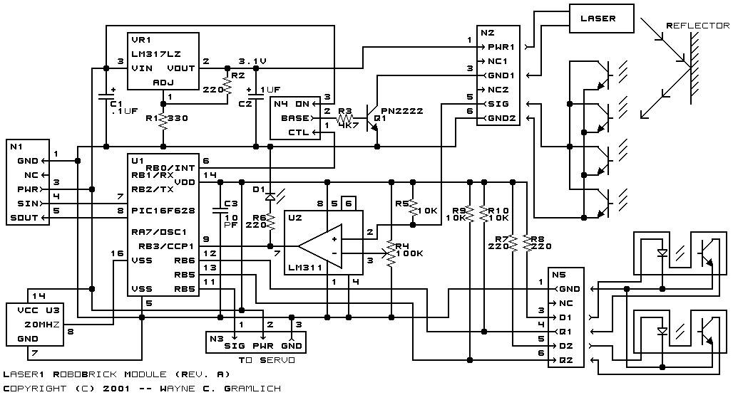
The hardware consists of a circuit schematic and a printed circuit board.
The schematic for the Laser1 RoboBrick is shown below:
The parts list kept in a separate file -- laser1.ptl. `
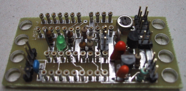
The printed circuit board files are listed below:
The Laser1 software is available as one of the followin:
The following fabrication issues came up: