This is the Revision A version of the Laser1 RoboBrick. The status of this project is that it has been replaced by the Revision B version.
This document is also available as a PDF document.
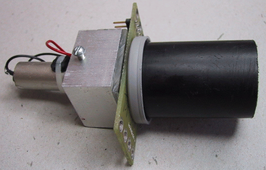
The LaserHead1 RoboBrick is a module that is designed to hold a slightly modified laser pointer and four photo detectors for the Laser1 RoboBrick.
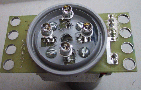
It has a central hole which the laser shines through. Around the hole are four photo detectors. In addition, there are four screw holes that can be used to mount the light shield bracket and the laser pointer bracket. There is a connector that is used to power the laser and read back the photo dectector voltage.
The hardware consists of a circuit schematic and a printed circuit board.
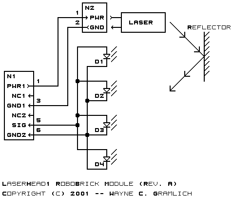
The schematic for the LaserHead1 RoboBrick is shown below:
The parts list kept in a separate file -- laserhead1.ptl.
The printed circuit board files are listed below:
The light shield is made out of a 35mm film cannister and its lid. The bottom is cut off the film cannister using a hack saw. The lid has a hole drilled in the middle. The lid is temporarily screwed to the center hole of the LaserHead1 board and used as a template to mark where the four screw holes need to be drilled. The lid is removed and the four mounting holes are drilled. Next, using a handheld hole punch, larger holes are cut for the photo detectors to fit through.
{There needs to be some additional plastic removed so that the soldered in detectors do not interfere with the plastic.}
The laser mounting bracket is constructed out of two 1 inch square pieces of 3/8 inch thick plastic. A cross is scribed into the square to find the center. A small guide hole is drilled in the center of both pieces. Each piece is mounted on the LaserHead1 board using a small screw. The LaserHead1 board is used a template to locate where the screw holes should be drilled. The four screw holes are drilled in each piece. The center hole of each piece is enlarged to a width just barely large enough to hold the laser pointer. Finally, one of the square piecs has a hole drilled on the side, that is tapped for a small set screw.
The photo dectectors and connector are soldered to the LaserHead1 board. The LaserHead1 is sandwiched between the 35mm lid and the two square pieces of plastic. Four screws are fed through the holes and capped with a washer, lock washer, and a nut. The laser pointer is fed into the center hole and secured in place with the set screw. The 35mm body is attached to the lid.
Two wires are attached to the laser pointer plus and minus leads and soldered to the LaserHead1 board. If you get the polarity reversed, it is quite likely that the laser pointer will die; so get it right! Use a nylon tie strip to permanently turn the laser on.
Run a cable between the Laser1 board and the LaserHead1 board. Plug the Laser1 board into a powered hub. Using a shorting block on the Laser1 board (N4), turn on the laser. Shine it at a reflector. Adjust R4 until the LED (D1) lights reliably when the laser beam hits a reflector. Disconnect the shorting block (N4). You are done.
The following issues came up: