This is the Revision D verion of the Digital8 module. The status of this project is finished.
This document is also available in PDF format.
The Digital8 module provides the ability to input and output 8 bits of digital data. The direction of each bit can be changed under program control.
The programmer can download a complement mask to cause any of the bits to be complemented prior to reading.
The Digital8 module supports the Interrupt Protocol. The interrupt pending bit is set whenever the the formula:
L&(~I) | H&I | R&(~P)&I | F&P&(~I)]is non-zero, where:
The Digital8 module supports both the standard shared commands and the shared interrupt commands in addition to the following commands:
Command Send/
ReceiveByte Value Discussion 7 6 5 4 3 2 1 0 Read Inputs Send 0 0 0 0 0 0 0 0 Return 8-bits of input iiii iiii (after XOR'ing with complement mask) Receive i i i i i i i i Read Outputs Send 0 0 0 0 0 0 0 1 Return 8-bits of the outputs oooo oooo (after XOR'ing with complement mask.) Receive o o o o o o o o Read Complement Mask Send 0 0 0 0 0 0 1 0 Return 8-bits of complement mask cccc cccc Receive c c c c c c c c Read Direction Mask Send 0 0 0 0 0 0 1 1 Return 8-bits of direction mask dddd dddd Receive d d d d d d d d Read Low Mask Send 0 0 0 0 0 1 0 0 Return 8-bits of low mask llll llll Receive l l l l l l l l Read High Mask Send 0 0 0 0 0 1 0 1 Return 8-bits of the high mask hhhh hhhh Receive h h h h h h h h Read Rising Mask Send 0 0 0 0 0 1 1 0 Return 8-bits of the rising mask rrrr rrrr Receive r r r r r r r r Read Falling Mask Send 0 0 0 0 0 1 1 1 Return 8-bits of the falling mask ffff ffff Receive f f f f f f f f Read Inputs Raw Send 0 0 0 0 1 0 0 0 Return raw inputs rrrr rrrr/Em> (no XOR with complement mask) Receive r r r r r r r r Read Analog Mask Send 0 0 0 0 1 0 0 1 Return 8 bit analog mask aaaa aaaa Receive a a a a a a a a Read Outputs Raw Send 0 0 0 0 1 0 1 0 Return raw outputs rrrr rrrr (no XOR with complement mask) Receive r r r r r r r r Read Analog Vref Send 0 0 0 0 1 0 1 1 Return analog Vref v Receive 0 0 0 0 0 0 0 v Reset Outputs Send 0 0 0 1 0 0 0 0 Set all 8 bits of outputs to 0 (then XOR with complement mask). Set Outputs Send 0 0 0 1 0 0 0 1 Set output bits to oooo oooo. Send o o o o o o o o Set Complement Mask Send 0 0 0 1 0 0 1 0 Set 8-bits of complement mask to cccc cccc Send c c c c c c c c Set Direction Mask Send 0 0 0 1 0 0 1 1 Set 8-bits of direction mask to dddd dddd 1=input; 0=output Send d d d d d d d d Set Low Mask Send 0 0 0 1 0 1 0 0 Set 8-bits of low mask to llll llll Send l l l l l l l l Set High Mask Send 0 0 0 1 0 1 0 1 Set 8-bits of the high mask to hhhh hhhh Send h h h h h h h h Set Rising Mask Send 0 0 0 1 0 1 1 0 Set 8-bits of the rising mask to rrrr rrrr Send r r r r r r r r Set Falling Mask Send 0 0 0 1 0 1 1 1 Set 8-bits of the falling mask to ffff ffff Send f f f f f f f f Set Outputs Raw Send 0 0 0 1 1 0 0 0 Set 8-bits to oooo oooo with no complement mask. Send o o o o o o o o Set Analog Mask Send 0 0 0 1 1 0 0 1 Set analog mask to mmmm mmmm. Receive a a a a a a a a Set Vref Mode Send 0 0 0 1 1 0 1 v Set Vref mode to v. Reset Everything Send 0 0 0 1 1 1 1 1 Reset all registers to 0 and set direction bits to 1 (input) Set Output Bit Send 0 0 1 0 v b b b Set output bit bbbb to v Set Outputs Low Send 0 1 0 0 l l l l Set low order 4-bits of Outputs to llll and then XOR complement mask Set Outputs High Send 0 1 0 1 h h h h Set high order 4-bits of Outputs to hhhh and and then XOR complement mask Set Direction Low Send 0 1 1 0 l l l l Set low order 4-bits of direction to llll. Set Direction High Send 0 1 1 1 h h h h Set high order 4-bits of direction to hhhh. Read Analog 8-bits Send 1 0 0 0 0 b b b Read 8-bits of analog data aaaa aaaa from port bbb. Receive a a a a a a a a Read Analog 10-bits Send 1 0 0 0 1 b b b Read 10-bits of analog data aaaa aaaa ll00 000 from port bbb. Receive a a a a a a a a Receive l l 0 0 0 0 0 0 Set Interrupt Commands Send 1 1 1 1 0 c c c Set Interrupt Command ccc. Shared Commands Send 1 1 1 1 1 c c c Execute Shared Command ccc
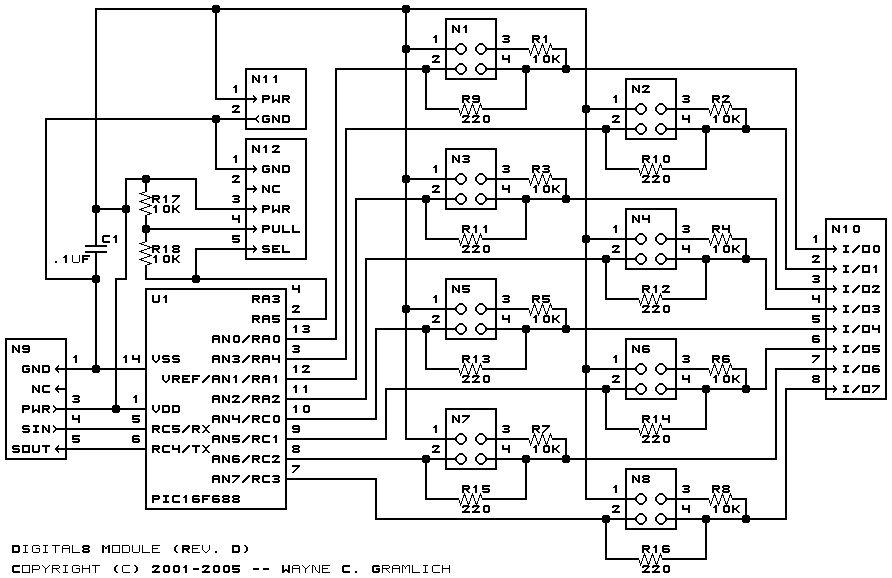
The hardware consists of a circuit schematic and a printed circuit board.
The schematic for the Digital8 module is shown below:
The parts list kept in a separate file -- digital8.ptl.
The printed circuit files are listed below:
The construction Instructions are located in a separate file to be a little more printer friendly.
The Digital8 software is available as one of:
Any fabrication issues will be listed here.