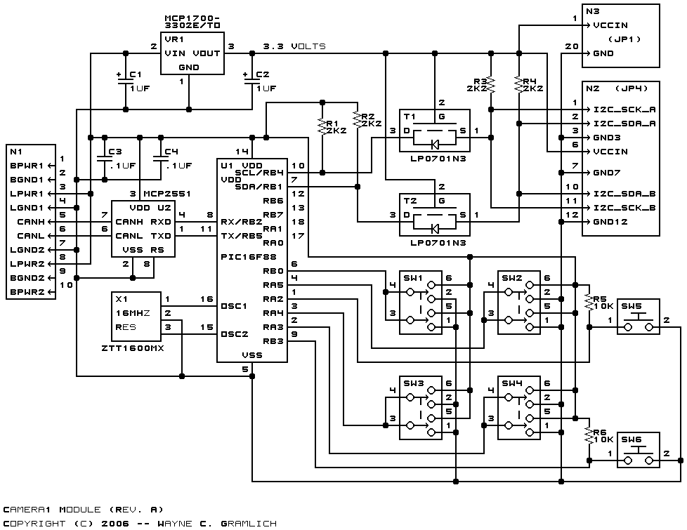
This is the revision A version of the Camera1 module.
The Camera1 module provides a RoboBricks2 bus interface for a General-Vision Cognisight MTVS vision system. This module a builtin camera and electronics for recoginizing features in an image. The recognition hardware is based on neural network technology.
At first, the module is trained on a bunch of image classes. After training, the module can recognize the various image classes it has been trained on. Up to 256 different image classes can be recoginized.
One of the switches on the board selects between master mode and slave mode.
To enter master mode, SW? is placed in the MASTER position. In master mode, this module will respond to the various buttons and switches on the board. In addition, the Camera1 module will find an LCD32 module on the RoboBricks2 bus to show status information.
The following butons are available:
- View/Learn Switch
- In view mode, the Camera1 module will send the currently recognized image off to the LCD32. In Learn mode, the remaining switches and buttons are used to train the camera to recognize images.
- Increment/Decrement Switch
- This switch specifies whether the [Bump] button will increment or decrement the id. Up to 256 separate image classes can be recognized.
- Bump Button
- Depressing this button will causes the image class number to be incremented or decremented.
- Add/Reset Switch
- This switch specifies whether the [Action] button will add another image or forget all previous images for the current id.
- Action Button
- This button causes another image to be taken with the camera and added to the current image class (add mode), or causes all images for the current image class to be rest (reset mode).
To enter slave mode, SW? is placed in the SLAVE position. In slave mode, all access and control of this module occurs via the RoboBricks2 bus. All other switches and buttons are ignored. The programming chart will eventually be shown below.
The hardware consists of a circuit schematic and a printed circuit board.
The schematic for the Camera1 module is shown below:
The parts list kept in a separate file -- camera1.ptl.
The printed circuit board files are listed below:
- camera1_back.png
- The solder side layer.
- camera1_front.png
- The component side layer.
- camera1_artwork.png
- The artwork layer.
- camera1.gbl
- The RS-274X "Gerber" back (solder side) layer.
- camera1.gtl
- The RS-274X "Gerber" top (component side) layer.
- camera1.gal
- The RS-274X "Gerber" artwork layer.
- camera1.gml
- The RS-274X "Gerber" mask layer.
- camera1.drl
- The "Excellon" NC drill file.
- camera1.tol
- The "Excellon" tool rack file.
The preliminary (i.e. does not work yet) Camera1 firmware is available below:
Any fabrication issues will be listed here.
The following additional documentation is available: