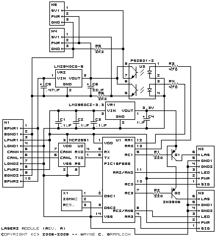
This is the Revision A verion of the Laser2 Module.
The Laser2 module provides the basis for a two laser bearing finders. This module can detect reflected back laser beam energy at supstantial distances (10+ meters.) Both reflective tape and bicycle reflectors make an excellent laser reflector. Please check the references section for more information. In particular, [Ubersitzig1999] is the root series of articles that motivates the desire for this sensor.
This module uses a sensor which has a laser pointer and light sensor mounted on a servo. In addition, there is a linear taper potentiometer set up as a linear voltage divider that tracks the servo position. The voltage is converted into a 10-bit value through an analog to digital converter. When the laser beam hits a piece of reflective tape, enough energy is reflected back to be detectable by the sensor.
Each time a Quick Set command is sent to the servo, the first and last registers are set to 0xffff (i.e. -1.) As the servo sweeps to its new location it records the potentiometer reading of the first time it notices laser light reflected back into the sensor and it remembers the last potentiometer reading at which laser light was detected. These two values stored in first and last respectively. Presumably, the average of these two values corresponds to the center of the reflective tape.
The Laser2 module can control two laser/servo/sensor combinations. There are two banks of control registers, one for each laser/servo/sensor unit. The register for each unit are:
Name Description Control Controls the enabling and disabling of both the servo and the laser. It also can reset the first and last register pairs. Servo High/Low This pair of registers specifies the servo pulse width in units of .2µSec. Thus, 7500 corresponds to 1.5mSec. First High/Low This pair of registers keeps track of the high and low of the potentometer settings when it first detect the laser light on the sensor. Last High/Low This pair of registers keeps track of the high and low of the potentometer reading when it last detected the laser light on the sensor. Potentiometer High/Low This pair of registers provides the current potentiometer reading as a value between 0 and 1023 inclusive.
The programming table lists all of the commands.
The hardware consists of a circuit schematic and a printed circuit board.
The schematic for the Laser2 Module is shown below:
The parts list kept in a separate file -- laser2.ptl.
The printed circuit board files are listed below:
The following files are available:
The following issues came up: