|
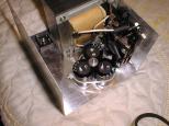
The 120VAC portion of the circuit is wired
together using 14AWG white solid copper wire.
I would have preferred a somwhat narrower gage,
but my local hardware store did not stock the
18AWG wire that I wanted. One end of the
switch is connected to the fuse holder and
the other end is connected to the line cord
plug. The other end of the line cord plug
is attached to the transform. The other end
of the transform is connected to the fuse holder.
The ground pin of the line cord plug is connected
to chasis using a piece of bare 14AWG wire.
Heat shrink tubing is threaded onto each wire
(except the ground wire.)
|
|
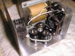
After the soldering is done, the heat shrink
tubing is positioned over the solder joint.
If you are lucky enough to have a heat gun,
use it to shrink the tubing over each solder
joint. I am not so lucky, so I use a matches.
The goal here is to make it difficult for
some idiot (like me) to accidentally reach
into the 120VAC section and get an electrical
shock.
|
|
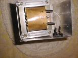
The output of the transformer is fed into the
the bridge rectifier using 14AWG white wire.
Again, pieces of heat shrink tubing are threaded
onto the wires.
|
|
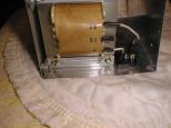
The heat shrink tubing is shrunk over each of
the connections. Also, I put heat shrink tubing
over the 12 volt center tap. I am a lot less
concerned about electrical shock on the 24VDC
section of the circuit, but avoiding accidental
shorts is work taking precautions for.
|
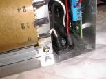
|
The 24VDC output from the bridge rectifier is
routed to the printed circuit board using
14AWG wire. The 24VDC line is red and the
ground return is black. Again, the heat
shrink tubing is pre threaded over the wires.
|
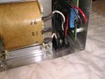
|
Again, the heat shrink tubing is shrunk to
seal the connection.
|
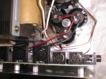
|
The capacitors are connected together using
14AWG wire. Again, red is 24VDC and black
is ground return. I could not figure out
how to easily do the heat shrink tubing thing,
so I just put gaps in the insulation.
|
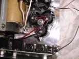
|
Each wire is carefully soldered. As you can
see, the red and black wires do not even touch.
|
|
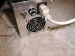
For the smoke test, the on/off switch
is turned off, the power cord is plugged
in, and the power plug is plugged into
an outlet strip (not shown) with a built
in circuit breaker.
|
|
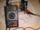
The DVM (Digital Volt Meter) is set up to
measure the voltage coming out of the
transformer. The power switch is flipped,
the voltage measures 22.5V and there is
much cheering. Yeah!!! (By the way, the
volt meter in the picture is reading 0.00
volts; this is because I have not flipped
the switch on yet.)
|


