|
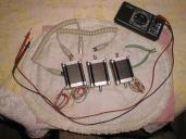
This picture shows all the stuff I used to
attach the stepper motors to DIN5 connectors.
The DIN5 connectors come off of a male to
male DIN5 cable, since I can not seem to find
DIN5 male connectors stand alone in a catalog.
The volt/ohm meter is used to figure out how to
which pin of the DIN5 connector goes to which
color of the cable.
|
|
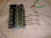
This picture shows three of the DIN5 connectors
snipped of the cables, wires sticking out,
stripped and twisted.
|
|
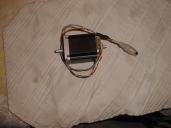
This shows what the cable looks like after it
has been attached to a stepper motor. I skipped
the step where I show each connection being
made and converted with heat shrink tubing.
The final mess is coverted with an even
bigger piece of heat shring tubing.
|
|
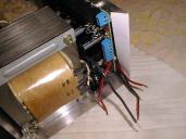
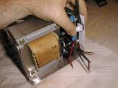
I just table some paper so that it folds over
the edge of the chasis. This is to help place
the estop (Emergency Stop) switch.
|
|
Next, I hold the switch on the back side
and carefully trace the perimeter of the
switch. (Yup, that's my hairy arm!)
|
|
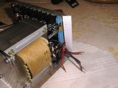
Afterwards the estop switch is traced. Now the
paper is flipped out, and I trace the perimeter
over to the other side.
|
|
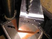
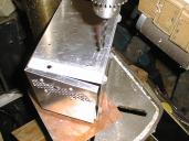
Finally, I drill the hole for the Estop switch.
|
|
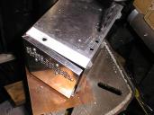
The hole for the green power LED is drilled next.
It just needs to fit under the PCB board.
|
|
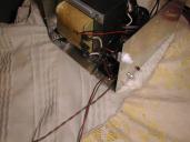
THe hole for the red fault LED is drilled next.
|
|
The Estop switch, power LED, and fault LED are
installed in position. When I took this picture,
the LED holder for the fault LED was not available.
(I forgot to order to of them.)
|


