|
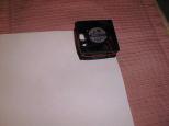
The fan is placed on the corner of an ordinary
piece of paper.
|
|
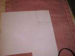
Using a pencil, the outline of the fan is traced
on the paper.
|
|
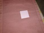
Using ordinary scissors, the outline is cut out.
|
|
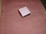
Using ordinary tape, the outline is taped to
the fan on the side that does not have any
struts holding the fan hub.
|
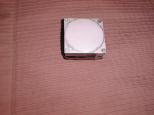
|
Using the side of an ordinary pencil lead,
the edges of the fan cavity and the mounting
holes are located. This is similar to placing
a piece of paper over a leaf and getting the
outline of the leaf. The result is kind of pretty.
|
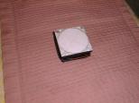
|
Using an ordinary ruler, draw two lines that
intersect in the center.
|
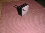
|
Using an ordinary drill bit that fits snuggly
in the hole, drill out the four corner holes.
The resulting holes are not very clean.
|
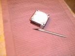
|
Using an ordinary sharp utility knife, clean of
the tags of paper on the holes.
|
|
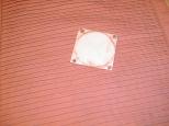
Using ordinary care, peel the paper template
off of the fan. There is no need to try and
remove the tape from the paper. Simply fold
the tape back over to back side of the paper.
|
|
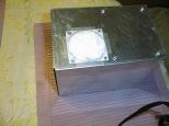
Again, using ordinary tape, place the template
in the desired location of the fan on the box.
I accidentally let the fan get too close to the
transformer, so I had to carefully loosen the
transformer screws, and slide it over just little
so that the fan would fit, and then re-tighten
the screws. I taped all four sides down.
|
|
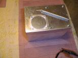
Using an ordinary utility knife, I carefully
cut the fan cavity outline out.
|
|
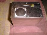
Using an ordinary sharp awl, I dimpled hole
starts for all four fan mounting holes.
|
|
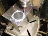
Using an ordinary drill press, I set up to
to drill the four mounting holes.
|
|
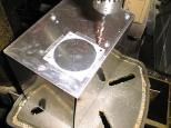
The first ordinary hole is drilled.
|
|
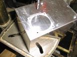
And the remaining three ordinary holes are
drilled.
|
|
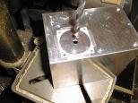
Using a larger ordinary drill, a large
starter hole was drilled in the center.
|
|
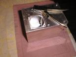
An ordinary nibbler tool is inserted
into the starter hole and the fan cavity
hole is nibbled out. The resulting edge
is quite rough, but the fan will never
know.
|
|
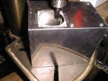
Using a rotary file in the drill press,
the rough edges are smoothed out.
|
|
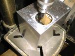
The resulting fan cavity hole is much
closer to circular.
|
|
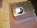
This is a somewhat clearer picture of
the same hole in better lighting.
|
|
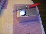
Using an ordinary round file, any left
over burrs are removed.
|
|
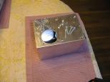
The fan is attached using 1-1/4 inch #6-32
round head screw, a lock washer, and 6-32
nut. The grill should help keep fingers
from touching the fan as it moves.
|
|
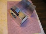
The screw goes through the grill first,
then the box, then the fan, then the
lock washer and finally the hex nut.
The result looks quite reasonable.
|


