|
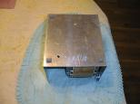
The rubber feet are installe first. (Note, I
accidentally deleted the first picture of the
rubber feet installation, so you see the two
holes drilled in the picture.)
|
|
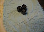
I use three Jameco 157737 10,000µF
capacitors to filter the 24VDC output
from the transformer. It is actually
easier to attach three capacitors to
the box than just one or two as I show
in the steps below. I use the two
nylon straps to help me out.
|
|
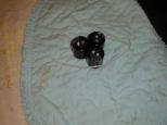
The three capacitors are grouped into a
triangle by using either one long nylon
tie strap, or two shorter ones arranged
in a loop. My long nylong tie straps
were not long enough, so I used two
shorter ones.
|
|
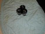
The nylon straps are tightened and the
ends that stick out are snipped off.
|
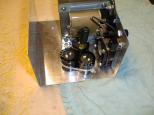
|
The capacitors are placed into the box
and a hole is dimpled using an awl for
the drill.
|
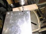
|
For me, it was easier to drill o n the bottom
of the box. Since it is really easy to see
where the dimple is on the bottom, I just
redimple the bottom and drill. (Note,
this picture is a retake, since I accidently
deleted the first one picture.) By the
way, I used a drill sized for a #6-32 hole.
|
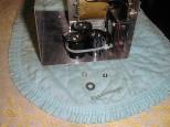
|
The capacitors are attached using a 2-inch
#6-32 round head screw, a #6 washer, a #6
lock washer, 1/4 inch washer, and a #6 hex
nut.
|
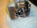
|
The 2-inch screw is placed through the
hole, the capacitors are center over the
screw, followed by the 1/4 inch washer,
followed by the #6 washer, followed by
the lock washer, and finally the #6 hex
nut. The #6 washer is too small to hold
the capaitors by itself, but in conjunction
with the 1/4 inch washer the capacitors
are held in place without any problems.
The lock washer keeps everything from
loosening up over time. The capacitors
are not going anywhere.
|
|
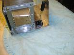
The bridge is Jameco 179477 and it is placed
next to the transformer and a hole is dimpled.
(Note: the original picture was accidentally
deleted; this is a retake.)
|
|
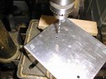
The hole is drilled from the bottom.
Again, the dimple location is easily visble
through the thin aluminim and I redimpled
the hole from the bottom. The hole is
size for a #10 screw.
|
|
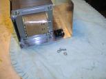
The bridge is attached using a 5/8" #10-32
round head screw, a #10 lock washer, and
#10-32 hex nut.
|
|
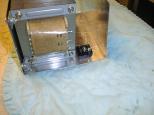
The #10-32 screw is placed through box hole
from the bottom. The bridge is placed over
the screw from inside the box. The bridge
is tighned down using a lock washer and a
#10-32 hex nut. That is it for the bridge
installation.
|


