|
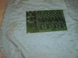
The bare controller board looks like this.
|
|
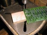
For revision D, the upper left mounting hole
is too close to N7.
|
|
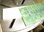
Luckily, there is plenty of space to the
lower left to relocate the hole down to.
|
|
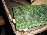
The DIN5 connectors N1 through N4 have there
mounting holes messed up. I need to redrill
all five holes.
|
|
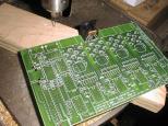
Here a DIN5 connector is installed in N3
using the new holes.
|
|
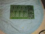
This is an upside-down view of the board
with the mounting hole relocated and all
4 DIN5 connectors redrilled.
|
|
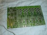
This is the upright view of the board
with the mounting hole relocated and all
4 DIN5 connectors redrilled.
|
|
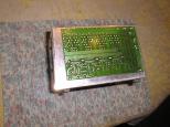
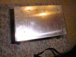
The board is very carefully placed
on the the box (opposite side from the fan
and power switch) and taped down. (This
picture is a retake, since I accidentally
deleted the original picture.) The DIN5
and DIN8 connectors need to be just under
the aluminium top. Similarly, the USB,
parallel port and serial port connectors
need to be positioned just behind the side
of the box. This is a little harder, since
all three of these connector hang over the
edge of the board.
|
|
The drill press is used to drill out each
of the mounting holes.
|
|
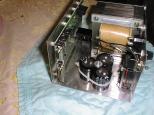
Now, the motion controller board is mounted on
3/8" #4-40 spacers with #4-40 round head screws
with a #4 washer. The board is attached to the
box using #4-40 round head screws. A number of
the conenctors are placed on the board to verify
the fit. In addition, the L298 with heat sink
is test placed to ensure that it does not run
into the the transformer. So, far everything
looks like it is going to fit just fine.
|
|
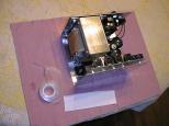
Now, comes the step of drilling holes in the
top of the box for the stepper motor connectors
(DIN5) and auxilary connectors (mini-DIN8.)
The DIN5 and mini-DIN8 connectors are press
fit into the printed circuit board. A piece
` of paper is cut out such that it will cover
all of the connectors ends.
|
|
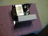
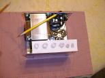
Using adhesive tape, the paper is attached
to the side of the box and folded over so
that the connectors are covered over.
|
|
Using a pencil, the edges of the connectors
are determined.
|
|
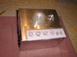
The paper template
is taped to the box lid.
|
|
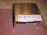
The box lid is removed and the flapping edge
is taped down.
|
|
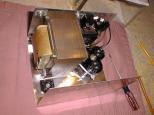
Now the printed circuit board is removed.
|
|
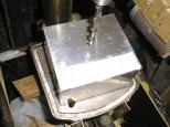
Now I took way too many pictures of the holes
being drilled out. Here is the box before
the first hole is drilled.
|
|
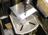
Here is the box after the first DIN5 hole
is drilled.
|
|
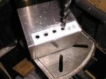
Here is the box after the all four DIN5 holes
are drilled.
|
|
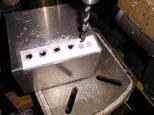
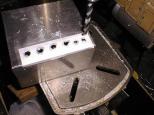
Now I change the drill bit and prepared to
drill out the mini-DIN8 holes.
|
|
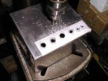
Now the mini-DIN8 holes are drilled.
|
|
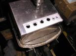
The DIN5 connector holes are too small, so
they need to be enlarged using a rotary file.
|
|
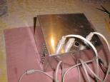
After enlargment they look as follows.
|
|
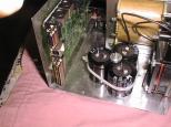
Using the DIN5 cables, the basic fit of the
holes is verified.
|
|
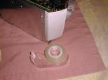
Now comes the fun of installing the DB9 connector
and a DB25 connector.
|
|
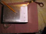
Using the same technique as before, a piece
of paper is cut out, taped to the box side,
and folded to cover the DB9 and DB25 connectors.
|
|
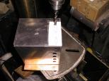
Using a pencil, the connector outlines are
marked.
|
|
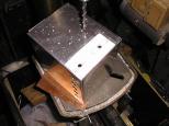
Using a drill big enough for the nibbler head,
a hole is drilled into the center of the DB25
connector outline.
|
|
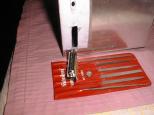
Using the same drill, the center of the DB9
connector is drilled out.
|
|
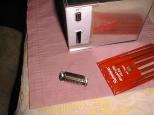
Using the nibbler tool, the connector outline
is nibbled out. Using some small files, the
final outline is filed out.
|
|
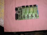
The DB9 connector is nibbled and filed out
as well. Please note that I used a random
male DB9 connector to do the final
nibbling and filing. The final connector
that is installed on the board is a female
DB9 connector. Also, there is a missing
photo where I drilled out the holes for the
DB9 and DB25 attachment spacers.
|
|
After all of that, the connectors are soldered
in. While I was at it, I soldered in the
IC sockets and screw terminals as well.
|
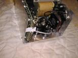
|
Now that the serial and parallel ports are
ready, it is time to make the hole for the
USB connector. The technique is the same
as always. A piece of paper is taped to
the box and folded to cover the USB connector.
|
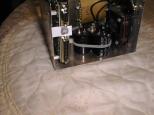
|
Using a pencil, the outline of the USB
connector is determined.
|
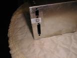
|
The printed circuit board is removed and the
box lid is installed. The paper is taped to
the box lid.
|
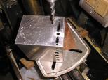
|
Using a drill that is a little smaller than
the USB connector, the hole is drilled.
The drill bit wandered a little, so my hole
was off center and got a little too close to
the parallel port connector.
|
|
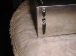
Using some small metal files, the round hole
is squared off to match the USB connector.
|
That is a good stopping point for mounting the board.


