|
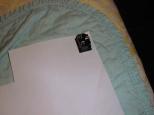
The power plug is Jameco 147109. It is placed
in the corner of pieceo of paper with a little
paper left around the edge.
|
|
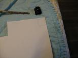
Using a pencil, the outline is traced.
|
|
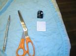
Using scisors, the piece of paper is cut out
leaving about an 1/8" round the traced outline.
|
|
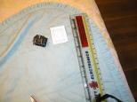
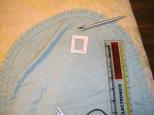
In fact, the hole to be nibbled needs to be
smaller than the traced outline. Using a
ruller, I marked off a boundary from the
traced outline. It is better to be too
small than too large.
|
|
Using a utility knife, the inside border
is cut out.
|
|
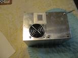
The template is taped to the box. This time
I made doubly sure that it would not get too
close to a transformer leg.
|
|
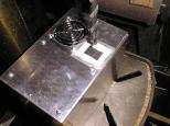
Getting ready to drill the starter hole for
the nibbler.
|
|
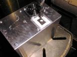
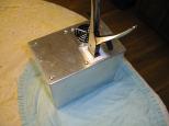
The head of the nibbler is pretty big, so
a pretty big drill hole is required.
|
|
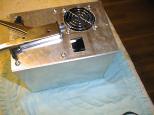
The resulting hole is big enough.
|
|
After the hole is nibbled out, the paper
template is removed. As I was getting close
to the template edges, I continually tried
fitting the plug in to make sure that the
hole I nibbled out was not too big.
|
|
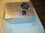
Afterwards, the plug is pushed in and
snaps right in. There is a small amount
of play afterwards (say 1/32"), but not
enough to matter.
|
|
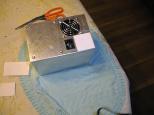
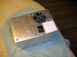
I cut a square of paper that
covers the remaining corner of the box.
|
|
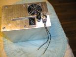
The square is taped down.
|
|
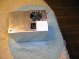
The fuse holder is Jameco 120993 and the power
switch is Jameco 76232. They are placed on the
paper square in the desired locations. A pencil
is used to trace the outlines.
|
|
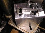
Using my ever trusty awl, I place dimples
where I want to drill the two holes.
|
|
The fuse holder diameter is measured to be
larger than the largest drill in my drill
box (1/2".) Bummer!
|
|
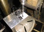
So, I use the 1/2" drill and drill the fuse
holder hole.
|
|
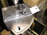
I peel back the paper square since it is not
needed anymore.
|
|
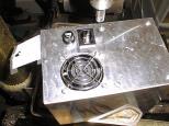
Using a rotary file mounted in the drill press
the 1/2" hole is enlarged. A circular motion
is used to enlarge the hole in all directions
at once. I kept enlarging the hole a little,
and test fitting the fuse holder. I had the
hole "just right" and then I slipped up when
the drill was spinning down gouged out a much
oblong hole that is significantly largere than
necessary. Next time I will let the bit spin
all the way down before touching the box.
|
|
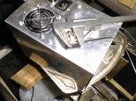
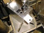
The switch is measured to be about 1/2" in
diameter.
|
|
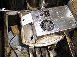
Using the same drill bit as before, the hole
is set up on the drill press.
|
|
The hole is drilled.
|
|
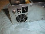
Finally, both the fuse holder and switch are
installed. So far, my mistakes have been small
enought so that they are not particularly visible.
|


