This is the Revision D version of the TwinGearSensorLeft RoboBrick. The status of this project is work in progress.

TwinGearSensorLeft Robobrick (Revision D)

Table of Contents

This document is also available in PDF format.

1. Introduction

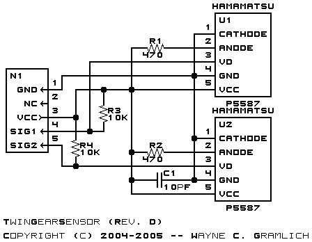
The TwinGearSensorLeft board is designed to pick up a quadrature signal from a shaft using two Hamamatsu P5507 chips.

2. Hardware

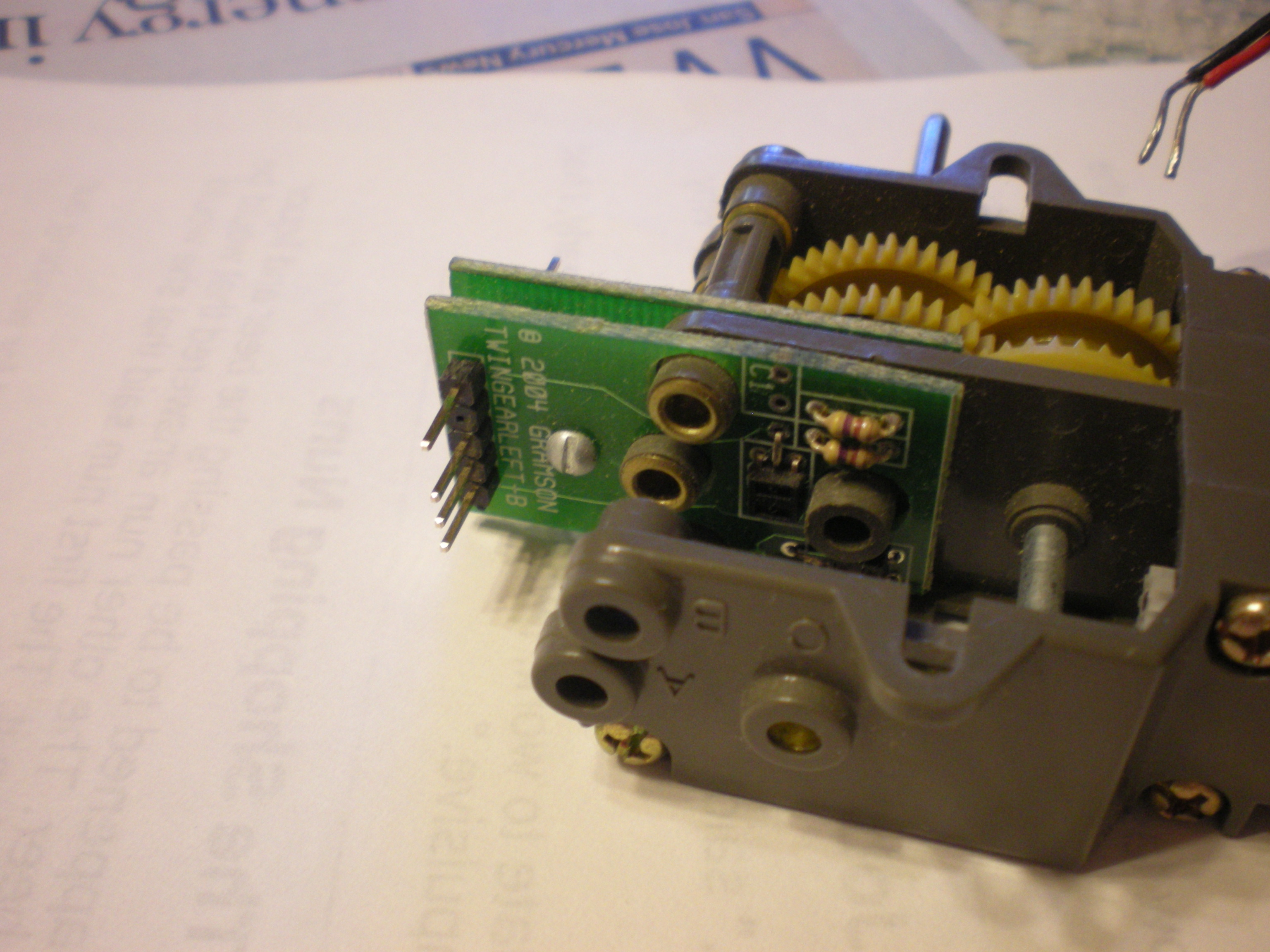
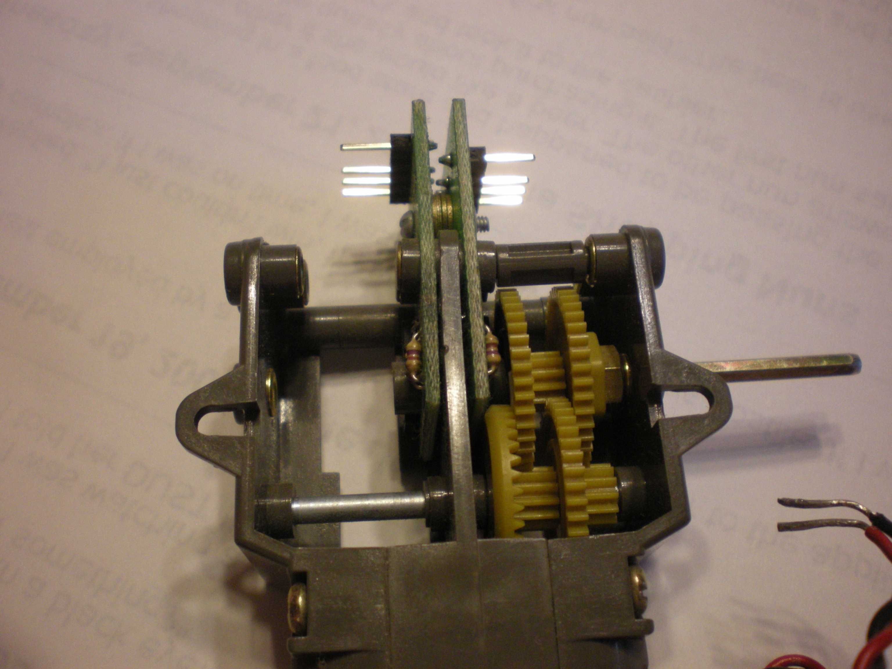
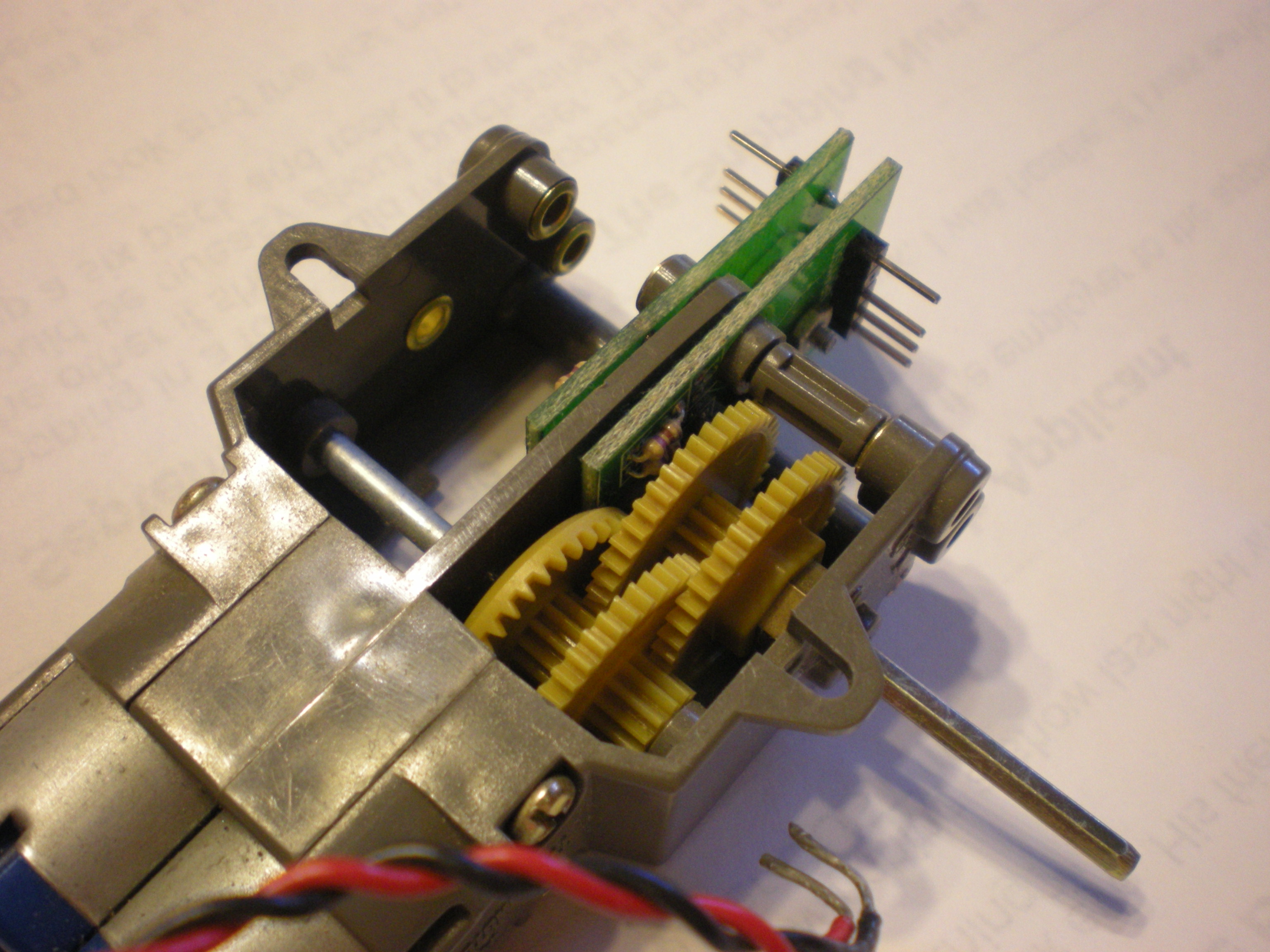
The hardware consists of a circuit schematic and a printed circuit board.

2.1 Circuit Schematic

The schematic for the TwinGearSensorLeft RoboBrick is shown below:

TwinGearSensorLeft Schematic

The parts list kept in a separate file -- twingearsensorleft.ptl.

2.2 Printed Circuit Board

The printed circuit board files are listed below:

twingearsensorleft_back.png
The solder side layer.
twingearsensorleft_front.png
The component side layer.
twingearsensorleft_artwork.png
The artwork layer.
twingearsensorleft.gbl
The RS-272X "Gerber" back (solder side) layer.
twingearsensorleft.gtl
The RS-272X "Gerber" top (component side) layer.
twingearsensorleft.gal
The RS-272X "Gerber" artwork layer.
twingearsensorleft.drl
The "Excellon" NC drill file.
twingearsensorleft.tol
The "Excellon" tool rack file.

3. Pictures


4. Issues

Any fabrication issues that come up are listed here.


Copyright (c) 2004 by Wayne C. Gramlich. All rights reserved.