This is the Revision H version of the Servo4 module. The status of this project is finished.
This document is also available as a PDF document.
The Servo4 module allows for the control of up to 4 hobby grade servos. It can be configured in the following ways:
Up to four RC servos are connected to connectors N2 (servo 0) through N5 (servo3). Each connector has the following pin definitions:
On many servos, the black wire is the ground wire. You will have to check you servo documentation to be absolutely sure though.
Pin Location Description 1 Left Servo control signal (varies between 0 and 5 volts) 2 Center 5 Volts 3 Right Ground (0 Volts)
The connection to the controlling module occurs via N1 in the upper left corner. Alternatively, in MSSC mode, the connection is via N12.
Power for the servos comes from N6, the blue two terminal connector in the upper right corner. Connect a power source of 6-12 volts to connector N6, where the upper terminal is the positive terminal ('+') and the the lower terminal is negative ('-'). The on board regulator, will regulate the voltage down to 5 volts for the servos.
The hardware configuration for each mode is summarized in the table below:
Mode Jumpers Trim Pots N7 N8 N10 N11 R4 R5 Pure Servo Mode Right (2-3) Right (2-3) Right (2-3) Off Unused Unused Differential Steering Mode Left (1-2) Left (1-2) Right (1-2) Off Servo 0 Stop Servo 1 Stop Differential Steering Calibration Mode Left (1-2) Left (1-2) Left (1-2) Off Servo 0 Stop Servo 1 Stop MSSC Compatibility Mode Left (1-2) Left (1-2) Right (1-2) On Address A2-A3 Address A4-A5
In differential steering calibration mode, N11 is jumpered to the left and it causes yellow LED D1 to light. It causes both servos 0 and 1 to be enabled. The value of trim pot R5 to be sent to servo 0 and trim pot R6 to be sent to servo 1. The purpose of calibration mode is to allow you to adjust the two modified servos that are connected to servo 0 and servo 1 and adjust them until they stop rotating. This frees the programmer from having to experiment to find the `position' number for each servo that corresponds to each servo being motionless. The values of the stop value are read out using the Read Current Draw command for servo 2 and 3.
In MSSC (Mini Serial Servo Controller) mode, all power comes in from the power source connected to N6 (the blue 2-terminal block.) No cable is connected to N1. In order to talk to the Servo4 module, a cable is constructed from a two pin male header and a female 9-pin DB9 connector. The connections are summerized in the table below:
From To Description DB9 Pin 3 2-pin Header Pin 1 Host Transmitted Data DB9 Pin 5 2-pin Header Pin 2 Ground (0 Volts) DB9 Pin 7 DB9 Pin 8 RTS to CTS DB9 Pin 4 DB9 Pin 1 and DB9 Pin 6 DTR to DSR and DCD
In MSSC (Mini Serial Servo Controller) mode, the servo board controls 4 servos at a time. An address is 6-bits long and is represented as a decimal number between 0 and 63 inclusive as shown below:
aa bb sswhere
Thus, to set the MSSC address to servo bank 0-3, both trim pots are turned full counter clockwise. Similarly, to set the MSSC address to servo bank 60-63, both trim pots are turned full clockwise.
Value Position 00 7:00 (full counter clockwise) 01 10:00 10 2:00 11 5:00 (full clockwise)
The Servo4 module can independently control up to 4 servos. Each servo has 1) an enable bit and 2) a current position. The position is represented as an 8-bit number. Some experimentation may be needed to determine how the 8-bit numbers correspond to actual servo positions. All servos are initialized to have the enable flags off.
In MSSC (Mini Serial Servo Controller) mode, commands are of the form:
nn,ppp[cr]
where
    0,128

    1,0

    255,63,255
Note that the last command consists of three comma
separated numbers; only the last two numbers are
used. Lastly, the receipt of the carriage return
automatically enables the servos.
The Servo4 commands are summarized in the table below:
The Servo4 module does not know the minimum and maximum extent for each servo. This has to be determined by experimentation.
Command Send/
ReceiveByte Value Discussion 7 6 5 4 3 2 1 0 MSSC Command Execute (Carriage Return) Send 0 0 0 0 1 1 0 1 Set position using previously sent MSSC servo number and position. Enable all four servos. MSSC Next Number (',') Send 0 0 1 0 1 1 0 0 Start next MSSC number. MSSC Decimal Digit ('0'-'9') Send 0 0 1 1 d d d d Next decimal digit of MSSC number, where dddd=0000 corresponds to '0' and dddd=1001 is a '9'. MSSC Ignore Send 0 0 x x x x x x If 00xx xxxx does not match one of the previous MSSC commands, it is simply ignored. Set High Send 0 1 h h h h s s Set high order 4 bits of servo ss to hhhh and set the remaining 4 low order bits to zero. .Set Low Send 1 0 l l l l s s Set the low order 4 bits of servo ss position to llll. Set Enable and Position Send 1 1 0 0 0 e s s Select servo ss and set its position to ppppppp and enable flag to e. Send p p p p p p p p Set Enable Flag Only Send 1 1 0 0 1 e s s Select servo ss and set its enable flag to e. Read Position Send 1 1 0 1 0 0 s s Return the current position pppppppp for servo ss. Receive p p p p p p p p Read Enable Send 1 1 0 1 0 1 s s Return the enable bit e for servo ss. Receive 0 0 0 0 0 0 0 e Read Enables Send 1 1 0 1 1 0 0 0 Return the enable flags eeee for all four servos. Receive 0 0 0 0 e e e e Set Enables Send 1 1 0 1 1 0 0 1 Set enable flags for all four servos to eeee. Send 0 0 0 0 e e e e Read Current Draw Send 1 1 0 1 1 1 s s Return the aaaaaaaa current draw for servo ss. Receive a a a a a a a a Shared Commands Send 1 1 1 1 1 c c c Execute shared command ccc.
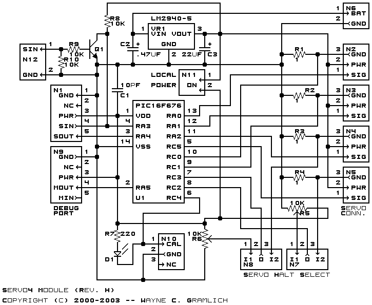
The hardware consists of a circuit schematic and a printed circuit board.
The schematic for the Servo4 module is shown below:
The parts list kept in a separate file -- servo4.ptl.
The printed circuit board files are listed below:
The Servo4 software is available as one of:
The following software issues have came up: