This is the Revision A verion of the Motor2 RoboBrick. The status of this project is work in progress.
This document is also available as a PDF document.
The Motor2 RoboBrick allows for control of up to two small DC motors via pulse width modulation.
The Motor2 RoboBrick can control up to two motors called 0 and 1 respectively. Each motor has a condition, power mode, direction, and speed. The condition is either on or off (i.e. freewheel.) The two power modes are pulsed and continous. The two directions are forward and backward. The speed is a number between 0 and 255 inclusive. There is one additional variable associated with each motor called ramp and a few additional variables that are shared between the two motors.
Pulsed mode is standard motor control via pulse width modulation (PWM.) When the speed is 0, no pulses are sent to the motor. When the speed is 255, the motor is full on. When the speed is 128, 50% duty cycle pulses are sent to the motor. The direction bit, controls what direction current is pulsed into the motor.
In continuous mode, power is continuously applied either forward or backward through the motor. In continuous mode, when the speed is 128, 50% duty cycle pulses are sent to the motor, where half the cycle is sends current forward through the motor and the other half is sends current backward through the motor (thereby cancelling out and resulting in a rotational speed of 0.) While continous mode consumes more power than pulsed mode, it sometimes provides better motor speed control at slow speeds.
The ramp variable is used to slow down the rate at which motor speeds are changed. When the ramp variable is non-zero, it specifies the rate at which motor speed changes (i.e. the speed ramp.) The ramp rate is measured in ticks (1/3 of a bit time at 2400 baud, or 1/7200, or 138µS. A ramp rate of 1, means the pulse widths will be changed every 138µS. A ramp rate of 100 means the pulse widths will be changed every 100 × 138µS or every 13.8mS. This allows the user to slowly speed up and slow down the motor. Please note, that ramp only applies to speed, changing the motor direction is immediate. (Sorry!)
For safety reasons, you might want the motors to shut off if the controlling program crashes. This is accomplished with a variable called the failsafe delay variable which is shared between both motors. When the failsafe delay variable is set to a non-zero value, it causes another variable called the failsafe counter to be initialized to the same value. Every 256 ticks (= 256 × 138µS = 35.5mS), the failsafe counter is decremented. If the failsafe counter ever decrements to 0, it immediately turns off both motors without any ramping. Every time a speed command is sent to the Motor2 RoboBrick, the failsafe counter is reinitialed to contain the failsafe delay variable. Thus, by occasionally sending commands that set the speed of either motor, the failsafe counter can be kept non-zero. Alternatively, there is a command that just reinitializes the failsafe counter without affecting the speed. The maximum amount of time between commands that reset the failsafe counter is 255 × 35.5mS or approximately 9 seconds. If the controlling program crashes, it will stop sending commands to the Motor2 RoboBrick and eventually, the failsafe counter will decrement to zero and stop both motors. There is yet a third variable called the failsafe error counter that is incremented each time a failsafe shut down occurs. The failsafe error counter can be read with yet another command. Lastly, both motors can be restarted by simply sending another command that sets the speed of either motor.
Finally, there is one other variable that is shared between the two motors called the prescaler. The prescaler is 3-bits wide and controls duty cycle width of the pulses are sent to the motor. The table below summarizes the prescaler to duty cycle relationship:
Prescaler Duty Cycle Width 000 .5µS 001 1µS 010 2µS 011 4µS 100 8µS 101 16µS 110 32µS 111 64µS
The Motor2 commands are summarized in the table below:
Command Send/
ReceiveByte Value Discussion 7 6 5 4 3 2 1 0 Set Quick Send 0 0 h h h h d m Set motor m speed to hhhh hhhh and direction to d (0=forward, 1=backward). Set Low Send 0 1 l l l l d m Set low order 4 bits of motor m speed to ll and direction to d (0=forward, 1=backward). Set Ramp Send 1 0 0 0 0 0 0 m Set the ramp for motor m to rrrrrrrr (00000000=no ramp (default)). Send r r r r r r r r Set Failsafe Send 1 0 0 0 0 0 1 0 Set the failsafe delay variable to ffffffff (00000000=off (default)). Send f f f f f f f f Reset Failsafe Send 1 0 0 0 0 0 1 1 Reset the failsafe counter to the failsafe delay variable. Set Speed Send 1 0 0 0 0 1 d m Set motor m to speed ssssssss and direction to d. Send s s s s s s s s Set Mode Send 1 0 0 0 1 0 x m Set motor m mode to x (0=pulsed (default), 1=continuous). Set Direction Send 1 0 0 0 1 1 d m Set motor m direction to d (0=forward (default), 1=reverse). Set Prescaler Send 1 0 0 1 0 p p p Set prescaler to ppp (000=fast, 111=slow (default)). Read Failsafe Send 1 0 0 1 1 0 0 0 Read the return the failsafe delay variable ffffffff. Receive f f f f f f f f Read Prescaler Send 1 0 0 1 1 0 0 1 Read the return the prescaler ppp. Receive 0 0 0 0 0 p p p Read Speed Send 1 0 0 1 1 0 1 m Read the return the speed ssssssss for motor m. Receive s s s s s s s s Read Mode/Direction Send 1 0 0 1 1 1 0 m Read the mode x (0=pulsed, 1=continuous) and direction d (0=forward, 1=reverse) for motor m. Receive 0 0 0 0 0 0 x d Read Ramp Send 1 0 0 1 1 1 1 m Read and return the ramp rrrrrrrr for motor m. Receive r r r r r r r r Read Failsafe Errors Send 1 0 1 0 0 0 0 0 Read and return the failsafe error counter eeeeeeee. Reset the counter. Receive e e e e e e e e Read Failsafe Counter Send 1 0 1 0 0 0 0 1 Read and return the failsafe counter cccccccc. Receive c c c c c c c c Read Actual Speed Send 1 0 1 0 0 0 1 m Read and return the actual speed for motor m Receive e e e e e e e e On/Off Send 1 0 1 0 0 1 o m Set motor m to condition o (0=off 1=on) Reset Send 1 0 1 0 1 0 0 0 Reset the entire motor controller Shared Commands Send 1 1 1 1 1 c c c Execute shared command ccc.
On power up, the Motor2 RoboBrick sets all variables to zero. The motor modes default to pulsed forward.
The hardware consists of a circuit schematic and a printed circuit board.
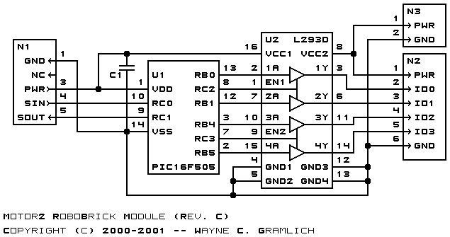
The schematic for the Motor2 RoboBrick is shown below:
The parts list kept in a separate file -- motor2.ptl.
The printed circuit files are listed below:
The Motor2 software is available as one of:
The Motor2 test suite is available as one of:
Any fabrication issues are listed here.