This is the Revision A version of the LCD32 RoboBrick. The status of this project is work in progress.
This document is also available in PDF format.
The LCD32 module can display a total 4 lines of 16 characters each, of which only 2 lines are visible at a time. The characters are displayed using a 5×7 dot matrix. There is a mechancal switch labeled LINES on the LCD32 module that switches between displaying lines 1-2 and lines 3-4. The LCD32 module is based upon the inexpensive Lumex® LCM-S01602DTR/M 2×16 liquid crystal display (LCD) module available from both Digikey® and Mouser®. The LCD32 module has a small trim potentiometer that allows you adjust the display contrast.
Most of the newer RoboBRiX™ modules have a 4-pin port labeled DEBUG. For modules that support the RoboBRiX debug protocol (some older firmware releases some do not drive the debug port), an LCD32 can be attached to the DEBUG port and display up to 32 hexadecimal bytes arranged as 4 lines of 8 bytes each. These bytes present the user with the internal state of each module. While it takes some effort to keep track of which byte is which, it is still way better than most modules which do not provide any view of the internal module state.
There is a second mechanical switch on the LCD32 module labeled MODE that switches the LCD module between DEBUG mode and REGULAR mode. In debug mode, characters inserted at the end of one line automatically show up on next line; this is called automatic line wrapping. Conversely, in regular mode, there is no automatic line wrapping and all characters output after the 16th character, will overwrite the 16th character.
The LCD32 module is meant to be used in conjunction with the LCD32Holder (Rev. A) board which carries the actual LCM-201602DTR/M and plugs onto the top of the LCD32 module.
| Command | Send/ Receive |
Byte Value | Discussion | |||||||
|---|---|---|---|---|---|---|---|---|---|---|
| 7 | 6 | 5 | 4 | 3 | 2 | 1 | 0 | |||
| Back Space | Send | 0 | 0 | 0 | 0 | 1 | 0 | 0 | 0 | Move cursor to the left. |
| Line Feed | Send | 0 | 0 | 0 | 0 | 1 | 0 | 1 | 0 | Advance currsor to beginning of next line; clear the next line |
| Form Feed | Send | 0 | 0 | 0 | 0 | 1 | 1 | 0 | 0 | Clear entire display and place cursor at home |
| Carriage Return | Send | 0 | 0 | 0 | 0 | 1 | 1 | 0 | 1 | Return cursor to beginning of line |
| Character 32 to 63 | Send | 0 | 0 | 1 | x | x | x | x | x | Enter the character on the display and advance cursor. |
| Character 64 to 127 | Send | 0 | 1 | x | x | x | x | x | x | Enter the character on the display and advance cursor. |
| Line Set | Send | 1 | 0 | 0 | 0 | 0 | 0 | l | l | Move cursor to line ll |
| Line Clear | Send | 1 | 0 | 0 | 0 | 0 | 1 | l | l | Move cursor to line ll and clear it |
| Cursor Mode Set | Send | 1 | 0 | 0 | 0 | 1 | 0 | v | b | Cursor mode is set (v=1 visible cursor) (b=1 blinking cursor) |
| Cursor Mode Read | Send | 1 | 0 | 0 | 0 | 1 | 1 | 0 | 0 | Read cursor mode (v=1 visible cursor) (b=1 blinking cursor) |
| Receive | 0 | 0 | 0 | 0 | 0 | 0 | v | b | ||
| Character Read | Send | 1 | 0 | 0 | 0 | 1 | 1 | 0 | 1 | Read the current character ccc cccc; advance cursor |
| Receive | 0 | c | c | c | c | c | c | c | ||
| Line Read | Send | 1 | 0 | 0 | 0 | 1 | 1 | 1 | 0 | Read the current line ll |
| Receive | 0 | 0 | 0 | 0 | 0 | 0 | l | l | ||
| Position Read | Send | 1 | 0 | 0 | 0 | 1 | 1 | 1 | 1 | Read the current character position pppp |
| Receive | 0 | 0 | 0 | 0 | p | p | p | p | ||
| Position Set | Send | 1 | 0 | 0 | 1 | p | p | p | p | Move cursor to character position pppp |
| Position Set | Send | 1 | 0 | 1 | 0 | p | p | p | p | Move cursor to character position pppp; clear to end of line |
| Shared Commands | Send | 1 | 1 | 1 | 1 | 1 | c | c | c | Execute shared command ccc. |
The hardware consists of a circuit schematic and a printed circuit board.
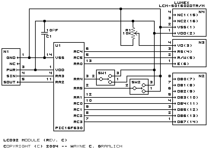
The schematic for the LCD32 RoboBrick is shown below:
The parts list kept in a separate file -- lcd32.ptl.
The printed circuit board files are listed below:
The LCD32 software is available as one of:
Any fabrication issues that come up are listed here.