| Command | Send/ Receive |
Byte Value | Discussion | |||||||
|---|---|---|---|---|---|---|---|---|---|---|
| 7 | 6 | 5 | 4 | 3 | 2 | 1 | 0 | |||
| Read LED's | Send | 0 | 0 | 0 | 0 | 0 | 0 | 0 | 0 | Return the four bits abcd that correspond to the LED's (a=left far, b=left near, c=right far, d=right near). |
| Receive | 0 | 0 | 0 | 0 | a | b | c | d | ||
| Read Left/Right Averages High Nibble | Send | 0 | 0 | 0 | 0 | 0 | 0 | 0 | 1 | Return the high order 4-bits of the left and right averages as llllrrrr where llll is the left nibble and rrrr is the right nibble. |
| Receive | l | l | l | l | r | r | r | r | ||
| Read Enables | Send | 0 | 0 | 0 | 0 | 0 | 0 | 1 | 0 | Return the illumination enable bits l and r. |
| Receive | 0 | 0 | 0 | 0 | 0 | 0 | l | r | ||
| Read Interrupt Mask | Send | 0 | 0 | 0 | 0 | 0 | 0 | 1 | 1 | Return the right average as rrrrrrrr. |
| Receive | 0 | 0 | 0 | 0 | 0 | 0 | l | r | ||
| Read Left Average | Send | 0 | 0 | 0 | 0 | 0 | 1 | 0 | 0 | Return the left average as llllllll. |
| Receive | l | l | l | l | l | l | l | l | ||
| Read Right Average | Send | 0 | 0 | 0 | 0 | 0 | 1 | 0 | 1 | Return the right average as rrrrrrrr. |
| Receive | r | r | r | r | r | r | r | r | ||
| Read Left Latest | Send | 0 | 0 | 0 | 0 | 0 | 1 | 1 | 0 | Return the left latest as llllll00. |
| Receive | l | l | l | l | l | l | 0 | 0 | ||
| Read Right Latest | Send | 0 | 0 | 0 | 0 | 0 | 1 | 1 | 1 | Return the right latest as rrrrrr00. |
| Receive | r | r | r | r | r | r | 0 | 0 | ||
| Read Left Far Threshold | Send | 0 | 0 | 0 | 0 | 1 | 0 | 0 | 0 | Return the left far threshold as llllllll. |
| Receive | l | l | l | l | l | l | l | l | ||
| Read Right Far Threshold | Send | 0 | 0 | 0 | 0 | 1 | 0 | 0 | 1 | Return the right far threshold as rrrrrrrr. |
| Receive | r | r | r | r | r | r | r | r | ||
| Read Left Near Threshold | Send | 0 | 0 | 0 | 0 | 1 | 0 | 1 | 0 | Return the left near threshold as llllllll. |
| Receive | l | l | l | l | l | l | l | l | ||
| Read Right Near Threshold | Send | 0 | 0 | 0 | 0 | 1 | 0 | 1 | 1 | Return the right near threshold as rrrrrrrr. |
| Receive | r | r | r | r | r | r | r | r | ||
| Read Left Delay | Send | 0 | 0 | 0 | 0 | 1 | 1 | 0 | 0 | Return the left delay as llllllll. |
| Receive | l | l | l | l | l | l | l | l | ||
| Read Right Delay | Send | 0 | 0 | 0 | 0 | 1 | 1 | 0 | 1 | Return the right delay as rrrrrrrr. |
| Receive | r | r | r | r | r | r | r | r | ||
| Set Enables | Send | 0 | 0 | 0 | 1 | 0 | 0 | l | r | Set the left enable to l and right enable to r. (1=on & 0=off) |
| Set Interrupt Mask | Send | 0 | 0 | 0 | 1 | 0 | 1 | 0 | 0 | Set interrupt mask to lllrrr where where lll is the left interrupt mask and rrr is the right interrrupt mask. |
| Send | 0 | l | l | l | 0 | r | r | r | ||
| Set Left Far Threshold | Send | 0 | 0 | 0 | 1 | 1 | 0 | 0 | 0 | Set Left Far Threshold to llllllll. |
| Send | l | l | l | l | l | l | l | l | ||
| Set Right Far Threshold | Send | 0 | 0 | 0 | 1 | 1 | 0 | 0 | 1 | Set Right Far Threshold to rrrrrrrr. |
| Send | r | r | r | r | r | r | r | r | ||
| Set Left Near Threshold | Send | 0 | 0 | 0 | 1 | 1 | 0 | 1 | 0 | Set Left Near Threshold to llllllll. |
| Send | l | l | l | l | l | l | l | l | ||
| Set Right Near Threshold | Send | 0 | 0 | 0 | 1 | 1 | 0 | 1 | 1 | Set Right Near Threshold to rrrrrrrr. |
| Send | r | r | r | r | r | r | r | r | ||
| Set Left Delay | Send | 0 | 0 | 0 | 1 | 1 | 1 | 0 | 0 | Set left delay to llllllll. |
| Send | l | l | l | l | l | l | l | l | ||
| Set Right Delay | Send | 0 | 0 | 0 | 1 | 1 | 1 | 0 | 1 | Set right delay to rrrrrrrr. |
| Send | r | r | r | r | r | r | r | r | ||
| Read Interrupt Bits | Send | 1 | 1 | 1 | 0 | 1 | 1 | 1 | 1 | Return the interrupt pending bit p and the interrupt enable bit e. |
| Receive | 0 | 0 | 0 | 0 | 0 | 0 | e | p | ||
| Set Interrupt Commands | Send | 1 | 1 | 1 | 1 | 0 | c | c | c | Set Interrupt Command ccc. |
| Shared Commands | Send | 1 | 1 | 1 | 1 | 1 | c | c | c | Execute Shared Command ccc. |
3. Hardware
The hardware consists of a circuit schematic and a printed circuit board.
3.1 Circuit Schematic
The schematic for the IRProximity2 module is shown below:
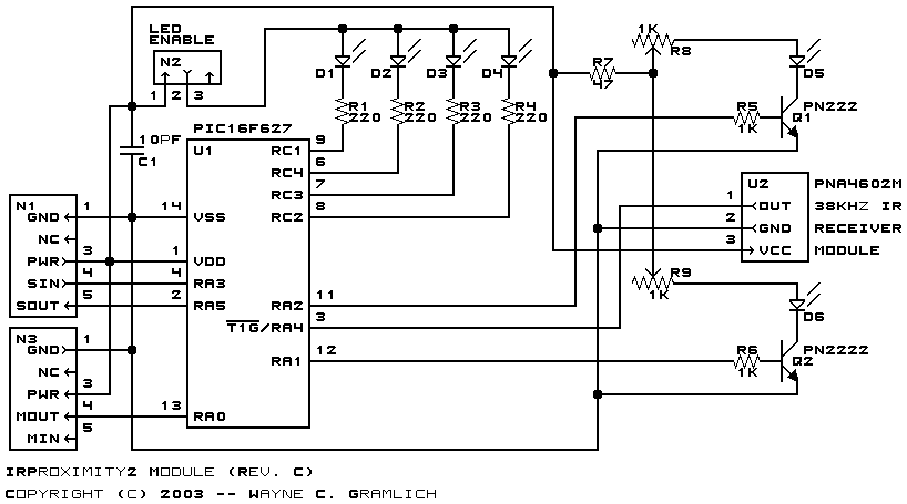
The parts list kept in a separate file -- irproximity2.ptl.
3.2 Printed Circuit Board
The printed circuit board files are listed below:
- irproximity2_back.png
- The solder side layer.
- irproximity2_front.png
- The component side layer.
- irproximity2_artwork.png
- The artwork layer.
- irproximity2.gbl
- The RS-274X "Gerber" back (solder side) layer.
- irproximity2.gtl
- The RS-274X "Gerber" top (component side) layer.
- irproximity2.gal
- The RS-274X "Gerber" artwork layer.
- irproximity2.drl
- The "Excellon" NC drill file.
- irproximity2.tol
- The "Excellon" tool rack file.
4. Software
The following software is available:
- irproximity2.ucl
- The µCL file that contains the firmware for the IRProximity2.
- irproximity2.asm
- The assembly file for the IRProximity2.
- irproximity2.lst
- The listing file for the IRProximity2.
- irproximity2.hex
- The Intel® Hex file for the IRProximity2.
5. Issues
The following fabrication issues came up:
- The artwork for D5 is wrong. The "+" should be on the lower pin.
- By design, IR Reciever has an enormous field of view. Without some amount of IR light shielding, no proximity detection occurs.
- The pots are turned in opposite directions to increase and decrease sensitivity. This needs to be fixed.
The following additions should be considered:
- Provide built in shielding.
- Provide the ability to change the IR LED power levels.
- Provide a way to mount the IR LED externally to get a wider separation.
Copyright (c) 2000-2004 by Wayne C. Gramlich. All rights reserved.