This is the Revision C verion of the IREdge4 module. The status of this project is finished.
This document is also available in PDF format.
The IREdge4 module can connect to up to 4 Photo Sensors (combined light emitter with photodetector.) The inputs are done using analog to digital converters rather than just binary inputs. There are 4 potentiometers to control the current throught the light emitters and 4 pententionmeters to control the gain of the returned signal.
The IREdge4 module is continuously reading the analog inputs from its four A/D pins. The controlling program can just read the results of the digital conversion, or it can have the result down converted into a single binary bit. Each pin has has a threshold high and threshold low register that is used for the down conversion. Whenever the digital conversion exceeds the high threshold register, the down coversion results in a 1. Whenever the digital conversion is lower than the low threshold register, the down conversion results in a 0. A hysterisis effect can be introduced by having some spread between the high and low threshold values.
After the down coversions to binary bits, the result is 4-bits of binary data. A complement mask can be used to selectively invert individual bits in the 4-bit data.
The IREdge4 module supports the Interrupt Protocol for those lines that are being used as inputs. The interrupt pending bit is set whenever the the formula:
L&(~I) | H&I | R&(~P)&I | F&P&(~I)is non-zero, where:
In addition to the common shared commands and the shared interrupt commands, the IREdge4 RoboBrix supports following commands:
| Command | Send/ Receive |
Byte Value | Discussion | |||||||
|---|---|---|---|---|---|---|---|---|---|---|
| 7 | 6 | 5 | 4 | 3 | 2 | 1 | 0 | |||
| Read Pin | Send | 0 | 0 | 0 | 0 | 0 | 0 | b | b | Read pin bb and respond with 8-bit value vvvvvvvv |
| Receive | v | v | v | v | v | v | v | v | ||
| Read Binary Values | Send | 0 | 0 | 0 | 0 | 0 | 1 | 0 | 0 | Return the binary values abcd (after XOR'ing with complement mask) |
| Receive | 0 | 0 | 0 | 0 | a | b | c | d | ||
| Read Raw Binary | Send | 0 | 0 | 0 | 0 | 0 | 1 | 0 | 1 | Return the raw binary values abcd (no XOR with complement mask) |
| Receive | 0 | 0 | 0 | 0 | a | b | c | d | ||
| Reset | Send | 0 | 0 | 0 | 0 | 0 | 1 | 1 | 0 | Reset everything to zero |
| Read Complement Mask | Send | 0 | 0 | 0 | 0 | 1 | 0 | 0 | 0 | Return the complement mask cccc |
| Receive | 0 | 0 | 0 | 0 | c | c | c | c | ||
| Read High Mask | Send | 0 | 0 | 0 | 0 | 1 | 0 | 0 | 1 | Return the high mask hhhh |
| Receive | 0 | 0 | 0 | 0 | h | h | h | h | ||
| Read Low Mask | Send | 0 | 0 | 0 | 0 | 1 | 0 | 1 | 0 | Return the high mask llll |
| Receive | 0 | 0 | 0 | 0 | l | l | l | l | ||
| Read Rising Mask | Send | 0 | 0 | 0 | 0 | 1 | 0 | 1 | 1 | Return the rising mask rrrr |
| Receive | 0 | 0 | 0 | 0 | r | r | r | r | ||
| Read Falling Mask | Send | 0 | 0 | 0 | 0 | 1 | 1 | 0 | 0 | Return the falling mask ffff |
| Receive | 0 | 0 | 0 | 0 | f | f | f | f | ||
| Read High Threshold | Send | 0 | 0 | 0 | 1 | 0 | 0 | b | b | Return high threshold for pin bb of hhhhhhhh |
| Receive | h | h | h | h | h | h | h | h | ||
| Read Low Threshold | Send | 0 | 0 | 0 | 1 | 0 | 1 | b | b | Return low threshold for pin bb of llllllll |
| Receive | l | l | l | l | l | l | l | l | ||
| Set High Threshold | Send | 0 | 0 | 0 | 1 | 1 | 0 | b | b | Set high threshold for pin bb to hhhhhhhh |
| Send | h | h | h | h | h | h | h | h | ||
| Set Low Threshold | Send | 0 | 0 | 0 | 1 | 1 | 1 | b | b | Set low threshold for pin bb to llllllll |
| Send | l | l | l | l | l | l | l | l | ||
| Set Complement Mask | Send | 0 | 0 | 1 | 0 | c | c | c | c | Set complement mask to cccc |
| Set High Mask | Send | 0 | 1 | 0 | 0 | h | h | h | h | Set high mask to hhhh |
| Set Low Mask | Send | 0 | 1 | 0 | 1 | l | l | l | l | Set low mask to llll |
| Set Rising Mask | Send | 0 | 1 | 1 | 0 | r | r | r | r | Set rising mask to rrrr |
| Set Falling Mask | Send | 0 | 1 | 1 | 1 | f | f | f | f | Set falling mask to ffff |
| Read Interrupt Bits | Send | 1 | 1 | 1 | 0 | 1 | 1 | 1 | 1 | Return the interrupt pending bit p and the interrupt enable bit e. |
| Receive | 0 | 0 | 0 | 0 | 0 | 0 | e | p | ||
| Set Interrupt Commands | Send | 1 | 1 | 1 | 1 | 0 | c | c | c | Set Interrupt Command ccc. |
| Shared Commands | Send | 1 | 1 | 1 | 1 | 1 | c | c | c | Execute common shared command ccc |
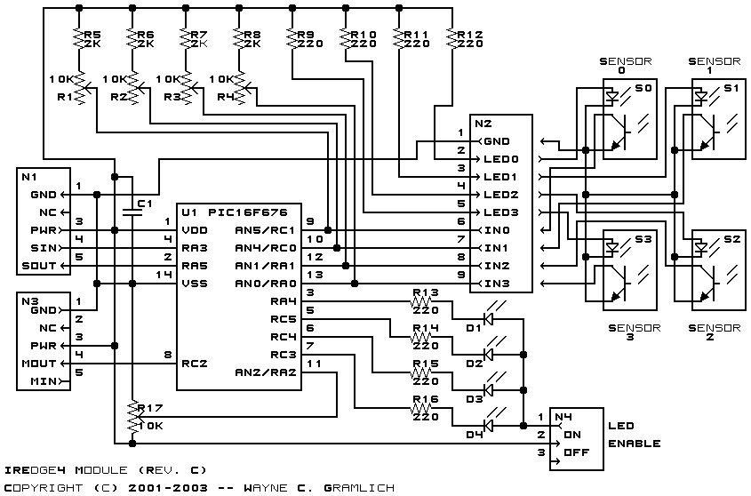
The hardware consists of a circuit schematic and a printed circuit board.
The schematic for the IREdge4 RoboBrix is shown below:
The parts list kept in a separate file -- iredge4.ptl.
The printed circuit board files are listed below:
The IREdge4 software is available as one of:
Any fabrication iusses will be listed here.