This is the Revision A verion of the IO8 Module. The status of this project is finished.
This document is also available in PDF format.
The IO8 Module is used to provide 8-pins of of I/O capabilitiy. Each I/O pin can independently used as digital input, an analog input, or a digital output. The analog input is at 10-bits or resolution based off of a internal 5-volt reference or an externally supplied voltage reference.
Module Interrupt Protocol for those lines that are being used as inputs. The interrupt pending bit is set whenever the the formula:
L&(~I) | H&I | R&(~P)&I | F&P&(~I)is non-zero, where:
In addition to the common shared commands and the shared interrupt commands, the AnalogIn4 Module supports following commands:
| Command | Send/ Receive |
Byte Value | Discussion | |||||||
|---|---|---|---|---|---|---|---|---|---|---|
| 7 | 6 | 5 | 4 | 3 | 2 | 1 | 0 | |||
| Read Inputs | Send | 0 | 0 | 0 | 0 | 0 | 0 | 0 | 0 | Return 8-bits of input iiii iiii (after XOR'ing with complement mask) |
| Receive | i | i | i | i | i | i | i | i | ||
| Read Outputs | Send | 0 | 0 | 0 | 0 | 0 | 0 | 0 | 1 | Return 8-bits of the outputs oooo oooo (after XOR'ing with complement mask.) |
| Receive | o | o | o | o | o | o | o | o | ||
| Read Complement Mask | Send | 0 | 0 | 0 | 0 | 0 | 0 | 1 | 0 | Return 8-bits of complement mask cccc cccc |
| Receive | c | c | c | c | c | c | c | c | ||
| Read Direction Mask | Send | 0 | 0 | 0 | 0 | 0 | 0 | 1 | 1 | Return 8-bits of direction mask dddd dddd |
| Receive | d | d | d | d | d | d | d | d | ||
| Read Low Mask | Send | 0 | 0 | 0 | 0 | 0 | 1 | 0 | 0 | Return 8-bits of low mask llll llll |
| Receive | l | l | l | l | l | l | l | l | ||
| Read High Mask | Send | 0 | 0 | 0 | 0 | 0 | 1 | 0 | 1 | Return 8-bits of the high mask hhhh hhhh |
| Receive | h | h | h | h | h | h | h | h | ||
| Read Rising Mask | Send | 0 | 0 | 0 | 0 | 0 | 1 | 1 | 0 | Return 8-bits of the rising mask rrrr rrrr |
| Receive | r | r | r | r | r | r | r | r | ||
| Read Falling Mask | Send | 0 | 0 | 0 | 0 | 0 | 1 | 1 | 1 | Return 8-bits of the falling mask ffff ffff |
| Receive | f | f | f | f | f | f | f | f | ||
| Read Raw | Send | 0 | 0 | 0 | 0 | 1 | 0 | 0 | 0 | Return 8-bits of raw input data rrrr rrrr (without XOR'ing with complement mask) |
| Receive | r | r | r | r | r | r | r | r | ||
| Read Analog Mask | Send | 0 | 0 | 0 | 0 | 1 | 0 | 0 | 1 | Return the Analog mask aaaa aaaa. |
| Receive | a | a | a | a | a | a | a | a | ||
| Read Outputs Raw | Send | 0 | 0 | 0 | 0 | 1 | 0 | 1 | 0 | Return the raw outputs as oooo oooo with no complement mask. |
| Receive | o | o | o | o | o | o | o | o | ||
| Read Analog VRef | Send | 0 | 0 | 0 | 0 | 1 | 0 | 1 | 1 | Return the analog Vref at v (0 = 5 volts, 1 = IO1). |
| Receive | 0 | 0 | 0 | 0 | 0 | 0 | 0 | v | ||
| Reset Outputs | Send | 0 | 0 | 0 | 1 | 0 | 0 | 0 | 0 | Set all 8 bits of outputs to 0 (then XOR with complement mask). |
| Set Outputs | Send | 0 | 0 | 0 | 1 | 0 | 0 | 0 | 1 | Set output bits to oooo oooo. |
| Send | o | o | o | o | o | o | o | o | ||
| Set Complement Mask | Send | 0 | 0 | 0 | 1 | 0 | 0 | 1 | 0 | Set 8-bits of complement mask to cccc cccc |
| Send | c | c | c | c | c | c | c | c | ||
| Set Direction Mask | Send | 0 | 0 | 0 | 1 | 0 | 0 | 1 | 1 | Set 8-bits of direction mask to dddd dddd 1=input; 0=output |
| Send | d | d | d | d | d | d | d | d | ||
| Set Low Mask | Send | 0 | 0 | 0 | 1 | 0 | 1 | 0 | 0 | Set 8-bits of low mask to llll llll |
| Send | l | l | l | l | l | l | l | l | ||
| Set High Mask | Send | 0 | 0 | 0 | 1 | 0 | 1 | 0 | 1 | Set 8-bits of the high mask to hhhh hhhh |
| Send | h | h | h | h | h | h | h | h | ||
| Set Rising Mask | Send | 0 | 0 | 0 | 1 | 0 | 1 | 1 | 0 | Set 8-bits of the rising mask to rrrr rrrr |
| Send | r | r | r | r | r | r | r | r | ||
| Set Falling Mask | Send | 0 | 0 | 0 | 1 | 0 | 1 | 1 | 1 | Set 8-bits of the falling mask to ffff ffff |
| Send | f | f | f | f | f | f | f | f | ||
| Set Outputs Raw | Send | 0 | 0 | 0 | 1 | 1 | 0 | 0 | 0 | Set 8-bits to oooo oooo with no complement mask. |
| Send | o | o | o | o | o | o | o | o | ||
| Set Analog Mask | Send | 0 | 0 | 0 | 1 | 1 | 0 | 0 | 1 | Set analog mask to aaaa aaaa. |
| Send | a | a | a | a | a | a | a | a | ||
| Set Analog VRef | Send | 0 | 0 | 0 | 1 | 1 | 0 | 1 | v | Set A/D converted Voltage refernce mode to v (0 = 5 volts, 1 = external). |
| Reset Everything | Send | 0 | 0 | 0 | 1 | 1 | 1 | 1 | 1 | Reset all registers to 0 and set direction bits to 1 (input) |
| Set Output Bit | Send | 0 | 0 | 1 | 0 | v | b | b | b | Set output bit bbbb to v |
| Set Outputs Low | Send | 0 | 1 | 0 | 0 | l | l | l | l | Set low order 4-bits of Outputs to llll and then XOR complement mask |
| Set Outputs High | Send | 0 | 1 | 0 | 1 | h | h | h | h | Set high order 4-bits of Outputs to hhhh and and then XOR complement mask |
| Set Direction Low | Send | 0 | 1 | 1 | 0 | l | l | l | l | Set low order 4-bits of direction to llll. |
| Set Direction High | Send | 0 | 1 | 1 | 1 | h | h | h | h | Set high order 4-bits of direction to hhhh. |
| Read Analog 8-bits | Send | 1 | 0 | 0 | 0 | 0 | b | b | b | Read 8-bits of analog value from bbb and returns result as aaaa aaaa. Note: there is a firmware bug that remaps the channels thusly CH0=IO3=N4-4, CH1=IO6=N4-7, CH2=IO5=N4-6, CH3=IO1=N4-2, CH4=IO0=N4-1, CH5=IO4=N4-5, CH6=IO2=N4-3, CH7=IO7=N4-8. |
| Receive | a | a | a | a | a | a | a | a | ||
| Read Analog 10-bits | Send | 1 | 0 | 0 | 0 | 1 | b | b | b | Read 10-bits of analog value from bbb and returns result as aaaa aaaa bb. See Read Analog 8-bits command for information about the channel remapping bug. |
| Receive | a | a | a | a | a | a | a | a | ||
| Receive | b | b | 0 | 0 | 0 | 0 | 0 | 0 | ||
| Read Low Threshold | Send | 1 | 0 | 0 | 1 | 0 | b | b | b | Read analog low threshold for bbb and returns result as llll llll. |
| Receive | l | l | l | l | l | l | l | l | ||
| Read High Threshold | Send | 1 | 0 | 0 | 1 | 1 | b | b | b | Read analog low threshold for bbb and returns result as hhhh hhhh. |
| Receive | h | h | h | h | h | h | h | h | ||
| Set Low Threshold | Send | 1 | 0 | 1 | 1 | 0 | b | b | b | Set the analog low threshold for bbb to llll llll. |
| Send | l | l | l | l | l | l | l | l | ||
| Set High Threshold | Send | 1 | 0 | 1 | 1 | 1 | b | b | b | Set the analog low threshold for bbb to hhhh hhhh. |
| Send | h | h | h | h | h | h | h | h | ||
| Set Interrupt Commands | Send | 1 | 1 | 1 | 1 | 0 | c | c | c | Set Interrupt Command ccc. |
| Shared Commands | Send | 1 | 1 | 1 | 1 | 1 | c | c | c | Execute Shared Command ccc |
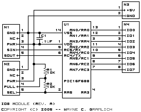
The hardware consists of a circuit schematic and a printed circuit board.
The schematic for the IO8 Module is shown below:
The parts list kept in a separate file -- io8.ptl.
The printed circuit board files are listed below:
The software for the IO8 is listed below:
Any fabrication issues will be listed here.