This is the Revision A verion of the
Harness RoboBrick. The status of this project is
it has been
replaced by the
Revision B version.
Harness Robobrick (Revision A)
This document is also available as a
PDF document.
The Harness RoboBrick is used to test a
RoboBrick network. It is built using a PIC16F84
microcontroller from
MicroChip. The PIC16F84 is used so that the
software can easily be changed for testing purposes.
Either a dumb terminal or a terminal emulator is
connected to the Harness RoboBrick via a
Tether RoboBrick. Communication occurs at
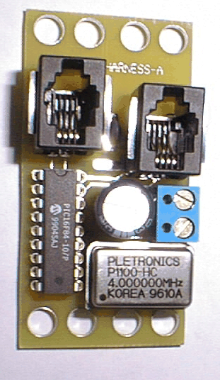
2400 baud. A picture of a Harness-A RoboBrick
is shown below:

The Harness commands are summarized as follows:
-
N
s -
Send N (where N is an
octal number) to the RoboBrick with
the high order two bits set. Do not wait
for any reply bytes.
-
N
w -
Send N (where N is an
octal number) to the RoboBrick with
the two high order bits set to '10'. The
program waits for response bytes until one
of the bytes comes back with the high order
bit set. All returned bytes are printed
as 3-digit octal numbers.
-
i -
Interrogate the RoboBrick to find out its
identification information.
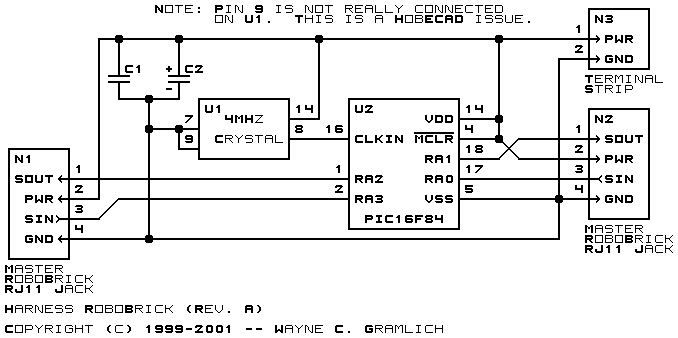
The hardware consists of a circuit schematic and
a printed circuit board.
The schematic for the Harness RoboBrick is shown below:

The parts list kept in a separate file --
Harness.ptl.
The printed circuit board files are listed below:
-
harness_back.png
-
The solder side layer.
-
harness_front.png
-
The component side layer.
-
harness_artwork.png
-
The artwork layer.
-
harness.gbl
-
The RS-274X "Gerber" back (solder side) layer.
-
harness.gtl
-
The RS-274X "Gerber" top (component side) layer.
-
harness.gal
-
The RS-274X "Gerber" artwork layer.
-
harness.drl
-
The "Excellon" NC drill file.
-
harness.tol
-
The "Excellon" NC drill rack file.
The Harness software is available as one of:
-
harness.ucl
-
The µCL source file.
-
harness.asm
-
The resulting human readable PIC assembly file.
-
harness.lst
-
The resulting human readable PIC listing file.
-
harness.hex
-
The resulting Intel® Hex file
that can be fed into a PIC12C5xx programmer.
The revision A Harness RoboBrick has the following
issues:
-
The Lego peg holes did not line up properly.
-
The pegs for the RJ11 sockets did not line up
properly.
-
The holes for the terminal block pins were too
small.
-
The bottom edge of the terminal block interfered
with the crystal. Move it up .05".
-
A tiny sliver of the terminal block is hanging
over the edge. Move it left by .05".
-
The electrolytic capacitor is too close to the
terminal block. Move it left by .05". This
may cause an interferance with the PIC.
-
There is plenty of space to move the RJ11 sockets
up.
-
Think about using a smaller crystal oscillator.
-
Add a power on LED.
-
Move the thick power trace away from the edge.
-
Add a reset button.
-
It might be nice to talk to two bricks at the
same time.
Copyright (c) 2000-2002 by
Wayne C. Gramlich.
All rights reserved.
