This is the revision D version of the Shaft2 module.
The Shaft2 module keeps track of two quadrature rotation sensors.
Command
NameAction Bit Description 8 7 6 5 4 3 2 1 0 Count Latch Send 0 0 0 0 0 0 0 0 0 Latch the current rotation count for both shafts. Count Clear Send 0 0 0 0 0 0 0 0 1 Clear rotation count for both shafts. Shaft High Get Send 0 0 0 0 0 0 0 1 s Read the latched 16-bit shaft value for shaft s. Return the high order 8 bits as hhhh hhhh. Save the low order 8 bits for the Shaft Low Get command. Receive 0 h h h h h h h h Shaft Low Get Send 0 0 0 0 0 0 1 0 0 Return the low order 8 bits of the last shaft read as llll llll. Receive 0 l l l l l l l l Common
CommandsSend 0 1 1 1 1 1 x x x Standard common command. See specifications for details. Receive 0 a a a a a a a a Select Send 1 a a a a a a a a Select the module with an address of aaaa aaaa. A time-out indicates that the module is not selected. Receive 0 1 0 1 0 0 1 0 1
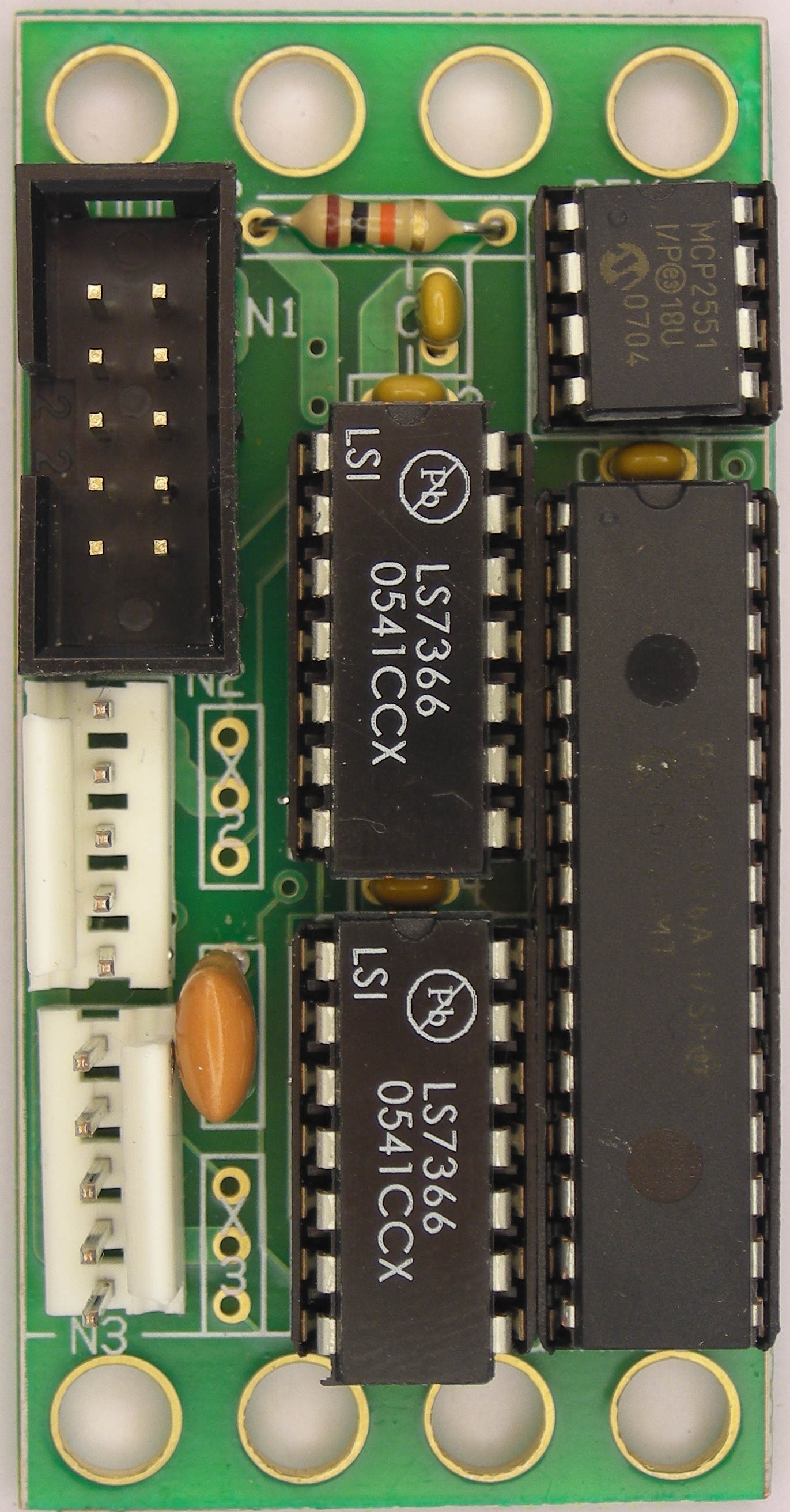
The hardware consists of a circuit schematic and a printed circuit board.
The parts list kept in a separate file -- shaft2.ptl.
The schematic for the Shaft2 module is shown below:
The printed circuit board files are listed below:
The following files are available:
The following fabrication issues came up:
The motors and shaft encoders that have been used with this module come from Solutions Cubed. In particular, the motor is the MOTOR1 and the encoder is the ENC300. The motor is available from alternate vendors such as Jameco. The encoders are actually from US Digital. The nice thing about Solutions Cubed is that they sell the motor, encoder, and encoder mounting kit all together, so there is no finger pointing if parts are missing.
The shaft encoder chip is the LS7366 from LSI Computer Systems and it is very difficult to obtain. I eventually wound up buying a tube of the chips from Gemini Electronics. When I called them I had to ask if they sold the chip, since it was not listed on their web site.
The encoders from US Digital conform to the following pin outs.
Note that the LS7366 must have a logic low voltage less than 1.0V and a logic high voltage above 3.5 volts.
Pin Usage 1 Ground 2 Index 3 A Channel 4 +5 Volts 5 B Channel
