This document is part of the RoboBricks2 project.
I am hopeful that various members of the Home Brew Robotics Club can come to agreement on a common connector and electrical specification so that there is a chance that we build robots that share one another's modules. If such a wonderful situation comes to pass, I would insist that we rename the bus to something a little more club centric, like Home Brew Bus. If not, oh well, it was a nice dream.
This document provides the electrical, protocol, and the electrical specifications for RoboBricks2. The most important aspect of this specification is the electrical specification, followed by the protocol, followed by the mechanical specification. Modules that are electrical and protocol compatible can be interoperated. The mechanical specifications are much more optional.
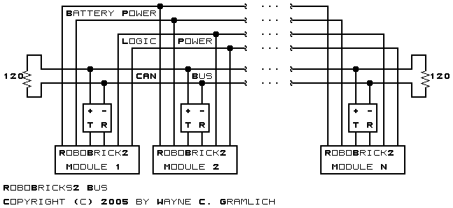
Each RoboBricks2 module plugs into a common 6-wire bus called the RoboBricks2 bus. (Hopefully, this will be renamed to a more appropriate name like HomeBrew Bus.) The 6 wires are organized in pairs where one pair provides a logic power supply, one pair provides a modest sensor/actuator power supply, and the remaining pair is used for inter-module communication. The inter-module communication is done using CAN bus (ISO 11898). A quick picture of the bus architecture is shown below:
The CAN bus transceiver chips are the small squares with the "+", "-", "T", and "R" in them. While this picture breaks out the CAN bus transceivers, they are in actually part of each RoboBricks2 module. Exactly one of the modules provides both regulated +5 volts and battery power to the logic power bus and battery power bus respectively.
The table below lists the RoboBricks2 bus wire names:
Name Description BPWR Battery Power Supply (6 - 9 Volts) BGND Battery Ground Return (0 Volts) LPWR Logic Power Supply (Regulated+5 Volts) LGND Logic Ground Return (0 Volts) CANH CAN Bus High CANL CAN Bus Low
The current RoboBricks2 bus is implemented via a 10 wire flexible ribbon cable based on the venerable .1 inch (2.54mm) IDC (Insulation Displacement Connection) connectors. It is both possible and legitimate to implement the RoboBricks2 bus using alternative connectors and cabling stratgies. However, the initial RoboBricks2 modules use the ribbon cable connectors.
The ribbon cable wires are organized as follows:
This wire organization has the following benifits:
Wire Name Usage 1 BPWR1 Battery Power Supply (1st wire) 2 BGND1 Battery Ground Return (1st wire) 3 LPWR1 Logic Power Supply (1st wire) 4 LGND1 Logic Ground Return (1st wire) 5 CANH CAN Bus High (+) 6 CANL CAN Bus Low (-) 7 LGND2 Logic Ground Return (2nd wire) 8 LPWR2 Logic Power Supply (2nd wire) 9 BGND2 Battery Ground Return (2nd wire) 10 BPWR2 Battery Power Supply (2nd wire)
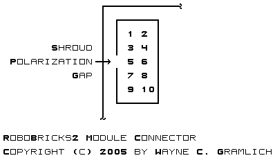
Each RoboBricks2 module has one shrouded and polarized 2×5 ribbon cable connector for attaching to the RoboBricks2 bus. The pin pitch is 2.54mm (.1 inch.) Whenever possible the connector is placed in the upper left corner of the module in a vertical orientation with the polarization notch pointing to the left. This is shown schematically below:
Cables consist of 2 or more 2×5 female IDC sockets attached to a length of ribbon cable. All of the sockets are oriented in the same direction. Cable cost is quite reasonable since a 2×5 IDC socket costs about $.25 in quantities of 10. Given the low connector cost, multiple connectors can be inserted in the middle of a longer ribbon cable.
Sometimes it will be inconvenient to use a single ribbon cable to connect all RoboBricks2 modules together. In this case a small splice module consisting of two shrouded 2×5 male connectors wired pin-to-pin can be used. Again, at $.35 in quanties of 25, a splice should have a material cost of approximately $1.
An extension cable can be made using a 2xtimes;5 female socket and a 2×5 male plug. Alas, the plug is fairly expensive.
While there is evidence that it is not strictly necessary to terminate the daisy chain with a termination resistor, a simple termination plug can be manufactured using a 2×5 shrouded header and a resistor. Thus, there is no real reason not to terminate a daisy chain.
Power needs to be provided to the RoboBricks2 bus. Most RoboBricks2 modules are power consumers. Some RoboBricks2 modules will choose to provide power to the bus. In general, there should only be one regulated supply providing power to the bus.
Due to the less than ideal conductor thickness for power transmission, it may be desirable to provide a splice module that allows power to be provided externally via thicker wires. This would ensure that all modules on the daisy chain get power at the required voltage.
The following prices are as of September 2005:
Part Number 1 Price 10 Price 100 Price 1000 Price Description Jameco 67811 .39 .35 .32 .28 2×5 Shrouded Polarized Male Header Jameco 32491 .29 .25 .19 .15 2×5 Polarized Female IDC Connector Mouser 579-MCP2551-I/P .86 .85 (for 50) .83 CAN Bus Transceiver (DIP8) DigiKey MKK10K-ND 2.95 2.49 (for 50) 2.24 1.85 2×5 Polarized Male IDC Connector
The RoboBricks2 protocol is expected to evolve over time. An overarching goal for the RoboBricks2 protocols is to keep them easy to use and easy to implement.
Protocols can range from very simple to quite complex. Whatever protocol ultimately gets adopted must be implemented by every module that connects to the RoboBricks2 bus. As the protocol complexity increases, the number of people who are able to implement requisite protocol in firmware decreases. Thus, it is important that the RoboBricks protocol remain relatively easy to implement, so that we keep the pool of people who want to implement a new RoboBricks2 module as large as possible.
This section describes a simple master/slave protocol that consists of a sending one or more request bytes followed by receiving zero, one or more response bytes. There are no sophisticated block counts, checksums, etc.
For the rest of this section, a `byte' is redefined to have 9-bits.
Each RoboBricks2 module has an 8-bit address. This allows for 256 addresses. Addresses 0 and 255 are reserved, just in case we need a global address.
The current plan is to use 9-bit serial protocol running at 500kbps. In 9-bit serial protocol, setting the 9th bit to 1 means that remaining 8 bits are an address. If the 9th bit is 0, the remaining 8 bits are data.
The initial protocol is quite simple. One module starts out being the bus master. Any time it needs to talk to another module, it simply sends out a module select command. After that, it sends commands to that module. When it needs to talk to another module, it selects a different module, thereby deslecting the previous module.
The table below shows the basic structure of master/slave communication:
Bit Action Description 8 7 6 5 4 3 2 1 0 Master decides to talk to a module. 1 a a a a a a a a Send Select module at address aaaa aaaa. 0 1 0 1 0 0 1 0 1 Receive Module responds with code 1010 0101 (0xa5) Send a command to module 0 c c c c c c c c Send Send command cccc cccc to module. Some commands require additional bytes of data to be sent. 0 r r r r r r r r Receive Receive a 0,1, or more byte response rrrr rrrr.
Each RoboBricks2 module has an address. This address can be changed! If two modules with the same address are plugged into the same RoboBricks2 bus, chaos ensues.
The address of any RoboBricks2 module can be changed putting the module on a bus where it is the only slave module. The master on the bus sends a set address command and the slave stores the address in its EEPROM somewhere. Since there is only one slave on the bus, only the one slave gets the new address.
While I expect modules to be implemented using a a variety of different microcontrollers, for the discusion below, I will assume the usage of one of the MicroChip PIC processors with the AUSART (Addressable Universal Synchronous Asynchronous Receiver Transmitter) modules.) The PIC AUSART has a two byte FIFO (First In, First Out) that can store two 9-bit bytes without suffering an overrun.
When a slave sends a response byte back to the master, the CAN bus transceiver will mirror the the byte back to the AUSART receiver. Since this happens everytime, the firmware can readily discard the sent byte. Since the AUSART has a FIFO of two bytes, the next byte that is received is the next command (or address select) byte from the master. Since there can be no buffer overrun, the slave is free to go off and do some time critical activities without having to worry about interrupts from the AUSART.
The AUSART has an additional control called ADEN (somtimes called ADDEN.) When ADEN is set, the AUSART will only receive bytes that have the 9th bit set. More precisely, the AUSAR will receive all bytes, but it will immediately throw away any bytes with the 9th bit clear; those with the 9th bit set get immediately placed into the FIFO. With ADEN clear, all bytes get placed immediately into the 9-bit FIFO.
The nice thing about the ADEN bit, is that it allows a slave modules on the RoboBricks2 bus to ignore traffic that is directed to other modules. The module only has to process bytes with the 9th bit set. The following rough code outline is worth looking at:
    # Initliaze UART:
    ADEN := 1
    while (True) {
	# Loop forever:

	while (UART_FIFO_EMPTY()) {
	    #do nothing
	}
	address_decode:
	select_address := UART_FIFO_READ()
	if (select_address == address_of_this_module){
	    # We are selected; clear ADEN:
	    ADEN := 0
	    # We now receive all bytes:

	    # Let the master know we are alive:
	    UART_SEND(0xa5)

	    # Swallow the echo:
	    while (UART_FIFO_EMPTY()) {
		# do nothing
	    }
	    zilch := UART_FIFO_READ()

	    # Process commands:
	    while (True) {
		# Wait for command:
		while (UART_FIFO_EMPTY()) {
		    #do nothing
		}
		address_bit := UART_FIFO_9TH_READ()
		command := UART_FIFO_READ()
		if (address_bit) {
		    # We have an address select:
		    select_addres := command
		    goto address_decode
		}
	        # Decode command:
 		#....
	    }

	} else {
	    # We are not selected; business as usual:
	    # ADEN is still set.
	}
    }
the AUSART will receive all data bytes. W When ADEN is set, the USART will only insxfxert bytes {Explain how ADEN works.}
{Explain how it is still necessary to clear out the FIFO of address select bytes when the slave is deselected.}
All RoboBricks2 modules must implement a basic set of common protocol commands. These commands are summarized below:
Command
NameBit Action Description 8 7 6 5 4 3 2 1 0 Select 1 a a a a a a a a Send Select the module with an address of aaaa aaaa. The response code rrrr rrrr specifies that the module is selected. A time-out indicates that the module is not selected. 0 r r r r r r r r Receive Deselect 0 1 1 1 1 1 1 1 1 Send Deselect the currently selected module. Acknowledge with aaaaaaaa (0=OK; all others are an error condition.) 0 a a a a a a a a Receive Id_Start 0 1 1 1 1 1 1 1 0 Send Return the number of bytes of identification ssss ssss. Subsequent calls to Id_Next will return byte bytes in sequence. 0 s s s s s s s s Receive Id_Next 0 1 1 1 1 1 1 0 1 Send Obtain the next identification byte iiii iiii. 0 i i i i i i i i Receive Address_Set 0 1 1 1 1 1 1 0 0 Send Set the node address to nnnn nnnn. oooo oooo is the old node address. 1010 0101 is returned if address is sucessfully set. 0000 0000 is returned any time an error is detected. 0 o o o o o o o o Receive 0 n n n n n n n n Send 0 n n n n n n n n Receive 0 n n n n n n n n Send 0 1 0 1 0 0 1 0 1 Receive
The identification string consists of a sequence of bytes. The total number of bytes in the identification string is returned by the Id_Start command. The bytes returned are listed below:
Sequence Bit Description 7 6 5 4 3 2 1 0 0 x x x x y y y y Id Format Version xxxx.yyyy. The first version is xxxx=0001 and yyyy=0000. 1 h h h h h h h h hhhh hhhh is the high 8-bits of the module identifier. 2 l l l l l l l l llll llll is the low 8-bits of the module identifier. 3 v v v v v v v v vvvv vvvv is the module revision. 4 0 0 0 0 0 l m v Feature mask: if v=1 => a vendor string follows, m=1 => module string follows, l=1 => loader support present.
The feature mask specifies additional features available on the module as described in the table below:
Bit Mask Name Description 0 0000 0001 Vendor String A vendor string follows. 1 0000 0010 Module String A module string follows 2 0000 0100 Loader Suppor Loader protocol is supported
Both the vendor and module strings (if present) have the format as shown below:
0 s s s s s s s s string size = ssss ssss 1 f f f f f f f f ffff ffff = first byte of string ... ssss ssss l l l l l l l l llll llll = last byte of string
Lastly, each different kind of RoboBricks2 module is assigned a 16-bit module identifier to distinguish it from other modules. The module identifiers are listed in the table below.
Id Module Name High Low 0 1 Laser1 0 2 MiniMotor2 0 3 MidiMotor2 0 4 IRDistance2 0 5 Shaft2 0 6 Orient5 0 7 Compass8 0 8 IO8 0 9 Sonar2 0 10 Voice1 0 11 Servo4 0 12 Camera1 0 13 Ether1 0 14 Flame1 0 15 IMU1 0 16 Sonar6 0 17 USB1 0 18 Wireless1 0 19 IRProximity4 0 20 MidiMotor1 0 21 MidiMotor1e 0 22 Laser2 0 24 Controller24 0 28 Controller28 0 32 LCD32 0 168 Controller168 (Mike Thompson)
Some of the RoboBrick2 modules will choose to implement the Loader protocol. The loader protocol is used to download code and/or data into a module. The loader protocol is summarized in the table below:
Command
NameBit Action Description 8 7 6 5 4 3 2 1 0 Loader Space Set 0 1 1 0 1 0 s s s Send Set the loader address space (000=Constants, 001=RAM, 010=Flash Code, 011=EEPROM) 0 1 0 1 0 0 1 0 1 Receive Loader Address Get 0 1 1 0 1 1 0 s s Send Return the ss'th byte of the loader address. (00=LSB, ..., 11=MSB) as aaaa aaaa. 0 a a a a a a a a Receive Loader Address Set 0 1 1 0 1 1 1 s s Send Set the ss'th byte of the loader address to aaaa aaaa (00=LSB, ..., 11=MSB). 0 a a a a a a a a Send 0 1 0 1 0 0 1 0 1 Receive Loader Data Get 0 1 1 1 0 0 c c c Send Return the ccc+1 bytes of data starting from the current loader address (and space). The loader address is incremented by ccc+1. aaaa aaaa is the first returned byte and hhhh hhhh is the 8th returned byte. 0 a a a a a a a a Receive ... 0 h h h h h h h h Receive Loader Data Set 0 1 1 1 0 1 c c c Send Set the next ccc+1 bytes of data starting from the current loader address (and space). The loader address is incremented by ccc+1. aaaa aaaa is the first stored byte and hhhh hhhh is the 8th stored byte. A status code of ssss ssss is returned (0000 0000=OK). 0 a a a a a a a a Receive ... 0 h h h h h h h h Receive 0 s s s s s s s s Receive Loader Execute 0 1 1 1 1 0 0 0 0 Send Start executing code at the loader address. Loader Application Resume 0 1 1 1 1 0 0 0 1 Send Return execution to the application. Return 0000 0000 for OK. 0 s s s s s s s s Receive Loader Enable 0 1 1 1 1 0 0 0 1 Send Enable the Loader 0 1 0 1 0 0 1 0 1 Receive
The concept behind the loader is that a microcontroller has up to 8 accessible address spaces. The first four address spaces are defined below:
Additional address spaces can be defined as needed, up to a total of 8 address spaces. Each space can be up 232 bytes in size, although most will be onsiderably smaller than that. The current address space to access is set using the Loader Space Set command.
Code Name 0 Constants 1 Flash Code (i.e. program) 2 RAM (Random Access Memory) 3 EEPROM (Electrically Erasable Programmable ROM)
The loader implements a single address register that is up to 32-bits in size. An individual RoboBricks2 module only needs to implement enough address bytes to access the all the bytes in all of the associated address spaces. For example, many 8-bit microcontrollers will choose to only implement 16 bits of address register. The Loader Address Set command is used to individual bytes in the address register. The Loader Address Get command is used to read back address register bytes. Unimplemented address register bytes are read back as 0.
Every RoboBricks2 module that implements the loader protocol must implement the constants address space. The constants address space contains information at fixed locations that specify the organization of the module. The constants are listed in the table below:
I toyed around with having individual commands to access the constant information, but it caused the loader code foot print to substantially larger. With constants, it is just a table lookup.
Address Name Description 0 Major Version The major version number for the constants address space. This starts at 1 and is incremented whenever an incompatible change occurs. 1 Minor Version The minor version number for the constants address space. This starts at 0 and is incremented whenever an compatible change occurs. 2 Address Space Count The number of address spaces on module. This number must be between 1 and 8. 3 Address Space Readable Mask A mask that indicates which address spaces a readable. 4 Address Space Writable Mask A mask that indicates which address spaces a readable. 5 Processor Architecture Indicates which processor architecture is implemented (0=PIC16, 1=PIC18, 2=AVR, 3=ARM) 6 Processor Identifier Processor ID (MSB) 7 Processor Identifier Processor ID (LSB) 8-11 Flash Space Size Number of bytes in Flash Space 12-15 RAM Size Number of bytes in RAM Space 16-19 EEPROM Size Number of bytes in EEPROM Space 20-23 Space 4 Size Number of bytes in Space 4 24-27 Space 5 Size Number of bytes in Space 5 28-31 Space 6 Size Number of bytes in Space 6 32-35 Space 7 Size Number of bytes in Space 7 36-37 Flash Page Size Number of bytes per Flash Page 38-39 RAM Page Size Number of bytes per RAM Page (almost always 1) 40-41 EEPROM Page Size Number of bytes per EEPROM Page (typically 1) 42-43 Space 4 Page Size Number of bytes per space 4 Page 44-45 Space 5 Page Size Number of bytes per space 5 Page 46-47 Space 6 Page Size Number of bytes per space 6 Page 48-49 Space 7 Page Size Number of bytes per space 7 Page 50 Flash Write Time Milliseconds required to write Flash Page 51 RAM Write Time Milliseconds required to write RAM (typically 0) 52 EEPROM Write Time Milliseconds required to write EEPROM 52 EEPROM Write Time Milliseconds required to write EEPROM 53 Space 4 Write Time Milliseconds required to write space 4 page 54 Space 5 Write Time Milliseconds required to write space 5 page 55 Space 6 Write Time Milliseconds required to write space 6 page 56 Space 7 Write Time Milliseconds required to write space 7 page
Data is read from and written to an address space using the Loader Data Get and Loader Data Set commands respectively. Obviously, attempting to write the constants address space will cause an error.
For address spaces that are implemented in EEPROM (Electrically Erasable Programmable Read Only Memory) sometimes referred to as "flash" memory, there are some issues associated with writing. In particular, some microcontrollers have restrictions on how their associated flash program memory is written. For microcontrollers that have page oriented "flash memory", the loader must have a page buffer. The page buffer is loaded each time a new memory page is accessed (read or write) and the page is flushed into flash memory whenever another address space or page is accessed. There may be a significant pause when the flush operation occurs, so the constants section suggests how long it takes to write a page sized chunk of flash memory in milliseconds. Since an error code is returned after every Loader Data Set, the pauses should be transparent to the accessing program. a
It is important to understand that this portion of the RoboBricks2 specification is optional. The modules designed by Wayne Gramlich and Bill Benson will adhere to these mechanical specifications, but other people may choose not to adhere to them. This is perfectly acceptable.
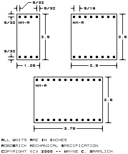
RoboBricks2 are compatible with the Lego®, MegaBloks®, and RokenBok® plastic toys. The standard pitch between studs on these toys is approximately 5/16 inches (or 4mm.) This means that a 4 by 4 square is 1.25 inches. The RoboBrick boards are always in units of 1.25 inch squares. All RoboBricks2 are 2.5 inches high by some multiple of 1.25 inches wide. Thus, the smallest RoboBrick is 1.25 by 2.5 inches, the next size up is 2.5 by 2.5, and the one after that is 2.5 by 3.75, etc.
The top and bottom of each RoboBrick has a row of holes that fit over the studs on plastic bricks. Thus, the holes are at least .195 inches in diameter. Since most RoboBrick printed circuit boards are double sided with plated through holes, the holes should probably be drilled with at least a .196 (#9) inch drill. For metric, a 4.9mm seems to work out reasonably well. The formula for determining the offset for stud N (where N starts at 0) is:
Offset = U/2 + N × Uwhere U is 5/16 of an inch. The expanded formula is:
Offset = .15625 + N × .31250The first 8 values for this formula are shown below:
After 8 entries, the numbers repeat offset by 2.5 inches.
Count Offset (in.) N×.05+/-offset 0 0.15625 3×.05+.00625 1 0.46875 9×.05+.01875 2 0.78125 16×.05-.01875 3 1.09375 22×.05-.00625 4 1.40625 28×.05+.00625 5 1.71875 34×.05+.01875 6 2.03125 41×.05-.01875 7 2.34375 47×.05-.00625 Repeats on 2.5 inch grid
Somewhere on each RoboBrick, must be name of the RoboBrick. The standard naming convention is `{name}-{revision}'. For example, 'Digital8-A', `DualMotor1Amp-B', etc. Please note that the revision corresponds to both hardware revision and the software revision inside the microcontroller.
A diagram of the mechanical specification is shown below: