This is revision B of the Mega1 module.
The Mega1 module can accept one of the many available 28-pin microcontrollers from Microchip® and Atmel.
This module has the following features:
This board supports the following Atmel microcontrollers:
You are free to program the microcontroller using any technology that you want. Two techniques are described here:
- External Programmer
- An external programmer can be used to program the microcontroller.
- Downloader
- A downloader executive can be programmed into the microcontroller, and programs can be loaded into the microcontroller via one of the serial communications connectors.
All terminal mode programs have the most significant bit cleared (i.e. plain ASCII) and all of the host commands start with the most significant bit set. This is summarized in the table below:
Bit Mode 7 6 5 4 3 2 1 0 0 x x x x x x x Text Mode Command 1 x x x x x x x Host Mode Command
Both terminal mode and host mode are discussed in separate sections below.
This level of protocol is not directly accessible to the user. This is just for documentation purposes.
The boot loader of the ATmegaxxx chip is programmed to enable the SPI interface in slave mode. The firmware in the PIC16F688 is programmed to send commands to the ATmegaxxx as an SPI master. This is done by bit banging (technical term.) Each time the PIC sends a command byte down, it gets also gets a byte of data back. The data returned is result of the previous command. There is a handshake line that is toggled after each SPI command is processed on the AVR. By watching the the handshake line, the PIC can not over run the AVR SPI slave command processor.
The command protocol is stateless in that every command is exactly one byte long. Thus, there is no way to get out of synchronization.
The commands are summarized in the table below:
Command
NameBit Returns Description 7 6 5 4 3 2 1 0 No-operation 0 0 0 0 0 0 0 0 0000 0000 Do nothing. Page Power Get 0 0 0 0 0 0 0 1 0000 0ppp Return ppp, the page size as a power of 2. Address Low Get 0 0 0 0 0 0 1 0 aaaa aaaa Return aaaa aaaa, the low byte of the address Address High Get 0 0 0 0 0 0 1 1 aaaa aaaa Return aaaa aaaa, the high byte of the address. Program Byte Get 0 0 0 0 0 1 0 0 pppp pppp Return pppp pppp, the next byte of program memory. Address is incremented. Address Jump 0 0 0 0 0 1 0 1 0000 0000 Jump to the address. Page Write 0 0 0 0 0 1 1 0 0000 0000 Page write. UART Status Get 0 0 0 0 0 1 1 1 0000 00ab Return the UART status as ab. UART Byte Get 0 0 0 0 1 0 0 0 0000 00ab Return the UART status as ab. Data Low Set 0 0 0 1 l l l l 0000 llll Set the low 4-bits of data to llll. Address Low Set 0 0 1 0 h h h h hhhh llll Set the low byte of address to hhhhllll, where llll is from the previous Data Low Set command. Address High Set 0 0 1 1 h h h h hhhh llll Set the high byte of address to hhhhllll, where llll is from the previous Data Low Set command. Byte Load 0 1 0 0 h h h h hhhh llll Load hhhhllll into the memory buffer, where llll is from the previous Data Low Set command. The address is incremented. Module Select 0 1 0 1 h h h h hhhh llll Send hhhhllll out to bus to select a module. llll is from the previous Data Low Set command. Byte Transmit 0 1 1 0 h h h h hhhh llll Send hhhhllll out to bus as a command/data byte. llll is from the previous Data Low Set command.
The hardware consists of a circuit schematic and a printed circuit board.
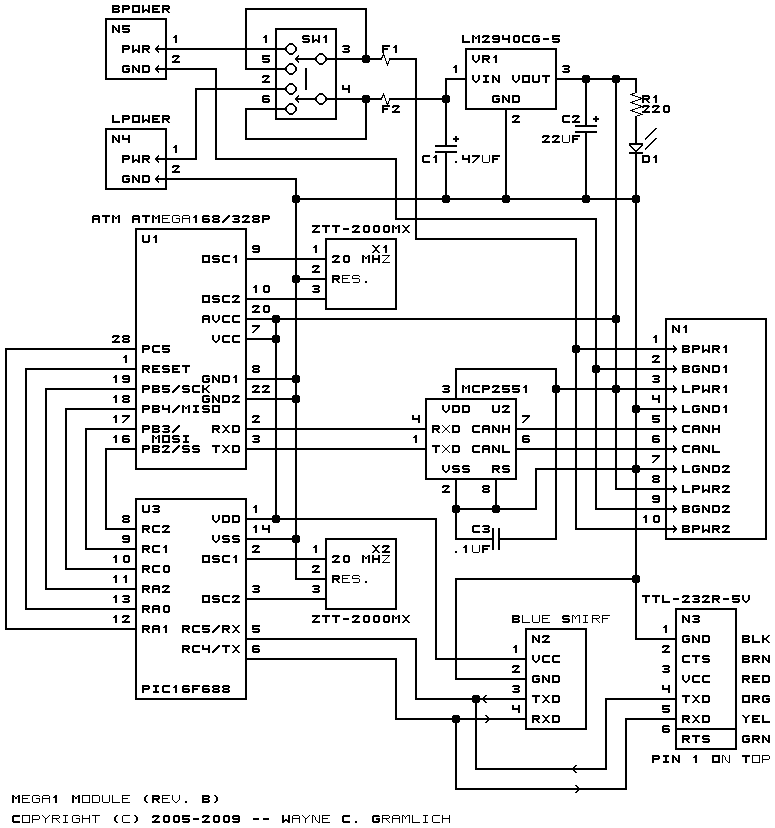
The schematic for the Mega1 module is shown below:
The parts list kept in a separate file -- mega1.ptl.
The printed circuit board files are listed below:
{To be written.}
Any issues that come are listed here.