This is the revision A version of the Controller28 module.
The Controller28 module can accept one of the many available 28-pin microcontrollers from Microchip®.
This module has the following features:
The following Microchip microcontrollers plug into this module:
You are free to program the microcontroller using any technology that you want. Three techniques are described here:
The rest of this section discusses the first downloader option.
- Downloader
- A downloader executive can be programmed into the microcontroller, and programs can be loaded into the microcontroller via the RoboBricks2 bus. The WireHost module can be used to facilitate this.
- ICD2 Header
- The ICD2 header can be hooked up to the Microchip ICD2 (In-Circuit Debugger). The ICD2 allows for microcontroller programming and program debugging with breakpoints.
- External Programmer
- An external programmer such as the Microchip PICStart+ or the KitsRUs K128/K149/K150/K182 can be used. The microcontroller chip is physically transfered between the programmer device and the 28-pin IC socket on the Controller28 board.
Command
NameAction Bit Description 8 7 6 5 4 3 2 1 0 Set Memory Address Send 0 0 0 0 0 0 0 0 0 Set the memory read/write address to hhhhhhhh:llllllll. Send 0 h h h h h h h h Send 0 l l l l l l l l Recieve 0 0 1 0 1 1 0 1 1 Read Memory Send 0 0 0 0 0 0 0 0 1 Read cccccccc words of program memory starting at the address recorded by Set Memory Address. The most significant byte comes first, followed by least significant byte. There are always cccccccc × 2 bytes returned. The 0x5c is always taked onto the end. Send 0 c c c c c c c c Receive 0 a a a a a a a a Receive 0 b b b b b b b b Receive ... Receive 0 z z z z z z z z Recieve 0 0 1 0 1 1 1 0 0 Program Word Send 0 0 0 0 0 0 0 1 0 Set the next word of program memory to hhhhhhhh:llllllll. Respond with rr equal to 3 for success, or 2, or 1 for failure. Send 0 h h h h h h h h Send 0 l l l l l l l l Recieve 0 0 1 0 1 1 0 r r Common
CommandsSend 0 1 1 1 1 1 1 x x Standard common command. See specifications for details. Receive 0 a a a a a a a a Select Send 1 a a a a a a a a Select the module with an address of aaaa aaaa. A time-out indicates that the module is not selected. Receive 0 0 0 0 0 0 0 0 0
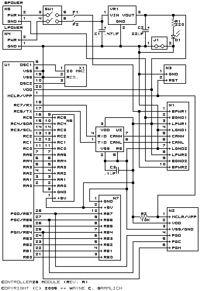
The hardware consists of a circuit schematic and a printed circuit board.
The schematic for the Controller28 module is shown below:
The parts list kept in a separate file -- controller28.ptl.
The printed circuit board files are listed below:
Unfortunately, there is not much standardization for In Circuit Serial Programming connectors. However most of the programmers that have ICSP support use some sort of 1×N male header with either .156" or .100" between the pins.
When it comes to in circuit debuggers for Microchip PIC microcontrollers there are few products to choose from. Indeed, as of October 2005, there are only three products I am aware of:
Microchip appears to have standardized on a 6-6 (6 position/6 wire) RJ11 connector and Olimex has standardized on a 1×6 .1" polarized connector. So even though there are only three products, there are already two connectors to choose from.
The Controller28 module uses the Olimex 1×6 header instead of the Microchip RJ11 connector. The reason for this is because there is simply insufficient room on the Controller28 board for the female RJ11 connector and everything else. Thus, the 1×6 is the only reasonable alternative.
The ICSP/ICD pins names, numbers, and descriptions are listed below:
A picture of the header is shown below:
- MCLR/Vpp (Pin 1)
- The is the pin used to reset the processor and to force the processor into programming mode.
- Vdd (Pin 2)
- The voltage that is being fed into the Vdd pin of the 28-pin processor (i.e. +5 volts.)
- GND (Pin 3)
- Ground.
- PGD (Pin 4)
- The program data pin on the 28-pin processor. This is sometimes called RB7.
- PGC (Pin 5)
- The program clock pin on the 28-pin processor. This is sometimes called RB6
- PGM (Pin 6)
- The low voltage program enter pin on the 28-pin processor. Microchip seems to have dropped this feature from their newer chips. The '16F87x chips seem to have it though.
The picture is a deep link into the Spark Fun PG2C Tutorial.
What if you have the Microchip ICD2 product and want to connect it to the Controller28 module? Well there are two options:
- Adaptor Cable
- The easies solution is to find a 6-wire cable with a 6-6 RJ11 connector on it, snip one end off, and splice on a 1×6 female header onto the other end.
- RJ11 to 1×6 Adaptor
- Alternatively, a adaptor between a 6-6 RJ11 and 1×6 polarized male header can be fabricated. If I get sufficiently motivated, I may even cook one up for laughs.
One comment, since the Microchip MPLAB® product does not currently run on Linux, I have used neither the Olimex nor Microchip in circuit debugger products. This ICSP/ICD facility is provided as a feature for people other than myself.
The following files are available:
The following fabrication issues were encountered: