This is the Layout Control LED Card identified in the
Layout Control Mother Board Design for the
MRNet project.
MRNet -- Layout Control LED Card
Table of Contents
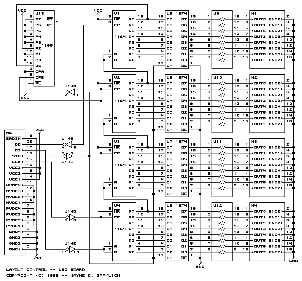
The purpose of the layout control LED card is
to provide an easy way to connect LED's to the
control system. The LED card provides connections
for up to 32 different LED's.
The layout control LED card is in the schematic below:

{Circuit description goes here.}
The layout control LED card has been layed out.
The following files are available:
-
LED Card PCB Artwork Layer
-
This contains the artwork layer that specifies
where the components are to be placed.
-
LED Card PCB Back Layer
-
This is the back (solder) side of the board.
-
LED Card PCB Front Layer
-
This is the front (component) side of the board.
-
LED Card PCB Excellon Drill File
-
This is the drill file for the PCB in industry
standard Excellon format.
-
LED Card PCB RS-274X Back Layer
-
This is the industry standard RS-274X file
that specifies the apertures and line placement
for the back layer.
-
LED Card PCB RS-274X Front Layer
-
This is the industry standard RS-274X file
that specifies the apertures and line placement
for the front layer.
-
LED Card PCB Drill Size File
-
This is a short file that specifies the drill
sizes for the Excellon drill file.
-
LED Card PCB Parts List File
-
This is the parts list file.
-
LED Card PCB Size and Hole Count File
-
This is a short file that specifies the board
size in inches and the total number of holes.
Copyright (c) 1999 by
Wayne C. Gramlich. All rights reserved.

