This document is part of my
MRNet project.
Walk Around Cab Box Construction
There are two choices when it comes to the cab box:
-
Use a preassembled box, or
-
Build a box from the ground up
Preassembled boxes are nice, until the vendor
decides to stop making them and then it is time
to rearrange the board to deal with the next
box. I would rather do everything once and be done
with it. I willl build the box from the ground up.
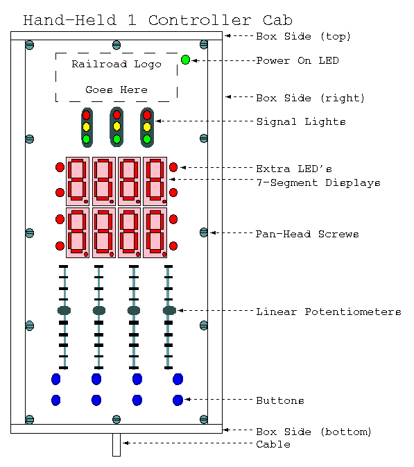
Below is a rough drawing of the front view of
the cab:

Below is the break down of the box parts:
-
Top Sheet
-
The top and bottom of the box are made out
of sheet aluminum. The aluminum sheet with
be of a thick enough gage to not flex too
much. Holes are drilled into the top sheet
for the buttons and the single LED's. A
nibbling tool is used to nibble out slots
for the linear potentiometers and the
7-segment displays. The controls are labeled
by printing a reverse image on some overhead
transparency, cutting it out, and wrapping
the edges around the top sheet, and taping
the edges to the buttom surface.
-
Bottom Sheet
-
The bottom sheet has the PC board attached
to it. It also provides a place to attach
the voltage regulator for a heat sink.
-
Printed Circuit Board
-
The current plans are to attempt to attach
all or the components on one side of the
board. The microcontoller and a few extra
chips are at the top of the board. This
results in a blank area at the top of the
box. This provides some extra blank space
to place a model railroad logo.
-
Box Sides
-
The box sides are made out of half round
plastic rod and quarter inch (~6.25mm)
thick sheet plastic. The half round
plastic rod can be manufactured by
taking a full round plastic rod and
cutting it in half on a band saw. The
quarter inch sheet is cut into long
thin strips on a band saw. The strips
thickness is such that they are slightly
thinner than the flat surface of the
half round stock -- by two pieces of
aluminum thickness and one sheet of
overlay plastic.
-
Attatchment
-
The cab has a 4-wire telephone
connector on the bottom for attaching
to the layout via a standard coiled
telephone handset cord. The cab
can be hung on the layout either by
an eye and hook arrangement where the
eye is at the top of the cab
and the hook is on the layout or by
Velcro (tm) attached to the bottom
of the box.
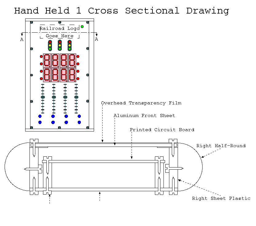
Below is a cross-sectional diagram of the
hand-held cab:

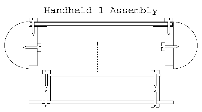
The box is assembled as follows:
-
Assemble the printed circuit board.
-
Top and bottom sheets of aluminum are cut to
exactly the same size. This can be done on
a band saw or by hand with tin snips.
-
(Optional) The aluminum surfaces are painted.
-
The control labels are printed in reverse on
overhead transparency film, cut out and taped
to the top surface. Care is taken to make
sure that there are tabs that extend out over
the edge of the top surface and are wrapped
around the top surface edges.
-
A drill press is used to drill holes for the
single LED's, the buttons, and the screws
around the edge that will attach the front
surface to the box sides. (Possible problem:
the drill press might chew up the overhead
transparency film; it may be necessary to
print two, and replace the film after
drilling.)
-
Use a nibbling tool to nibble out the slots
for the linear slide pots. Use the nibbling
tool to nibble out bit holes for the 7-segment
LED displays.
-
Make sure that the single LED's, buttons,
7-segment LED's and the slide potentiometers
all fit into their appropriate holes.
-
Take the long quarter inch plastic strips
and place them under the attachment holes
on the front panel. Mark where the holes
are and drill them with a drill press.
Use a tap to tap threads into the holes.
Use pan head screws to attach the front
surface to the side. Do the left and right
sides first, then the top and botom sides
second. Remember to drill a hole in the
bottom side for the 4-wire connector; use
a file to square off the hole.
-
Take the bottom surface and drill the
holes around the outside edge for the
attachement screws. Use an extra copy
of the overhead transparaency to place
the drill holes. Make sure that the
holes line up with the holes in the
long plastic strips. Do not
screw the bottom on yet.
-
Mount the printed circuit board on spacers.
-
Put down the bottom surface first, the
printed circuit board on spacers second,
and the top surface with sides third.
Everything should fit. Taking care not
to jar the printed circuit board, carefully
lift the top surface off. Using a felt
tip marker, draw circles on the bottom
surface around the spacers. Drill
holes for the spacers. Attach the
printed circuit board to the bottom
surface using pan head screws. Re-verify
that everything fits.
-
Unscrew the top surface from the sides.
Attach the half round stock to the
sides. Either use cynoacrylic glue
or drill, tap and screw.
-
Screw everything together.
That is it.

Copyright (c) 1997-1999 by
Wayne Gramlich All rights reserved.
