This is just some FunCAD documentation that I am working on. This project is work in progress.
Currently, the command line interface to FunCAD is
quite simple. You can specify zero, one or more
FunCAD files on the command line at start-up and
FunCAD will read those files in and add them to
the design tree. Currently, each FunCAD file ends
in the suffix .fcd (for FunCAD.)
For example,
prompt> funcad part1.fcd part2.fcd
will start FunCAD and read in the
part1.fcd and
part2.fcd files.
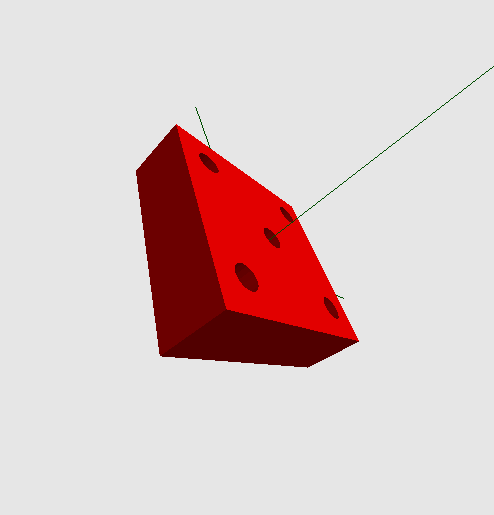
The 3D model is shown in the lower right corner of the window as follows:
The model above started off as a solid block of material that is 6 × 6 × 2 and drilled 5 holes through it.
The basic idea behind FunCAD is that you start with block, cylinders, and/or tubes of materials and then perform standard machining operations on them to produce the final part. Example machining operations are drilling, fly cutting, milling a pocket, cutting, bending, etc.
While conceptually the underlying 3D solids library that performs these operations should have no restrictions, the reality is that the library is quite buggy and will sometimes refuse to do some fairly easy operations. Luckily, rather than crashing outright as it used to do, the problem is usually detected, generates a rather useless (to you) error message, and leaves you in a position to try something else. It is going to be a long struggle to track down and fix all of the bugs in the 3D solids library.
Here are some hints of things not to try:
The view controls are in the upper left corner as shown below:
All reposition and reorient operations in FunCAD use the same basic Move/Tilt/Move model. First, the rotation origin is selected (i.e. "Move1"). Second, the object is reoriented in pitch, yaw, and roll (i.e. "Tilt"). Finally, the object is repositioned for final viewing (i.e. "Move2").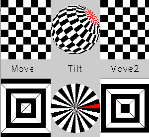
There are actually two coordinate axes -- one in green and the other in black. The two axes start out aligned with one another can can not be distinguished. The reorientation always takes place with the green axes. The black axes are always the reference coordinate system for the object.
The "Move1" repositions the object with respect to the orientation axis. It uses the checker board position control in the upper left to reposition in X and Y. Just click the left mouse button down over the checkboard and move the mouse around with the button depressed to see it in action. The nested black and white squares in the lower left are a zoom control for moving in the Z direction. Like the position control, just click down the left mouse button and somewhere on the zoom control and move the mouse towards the center to zoom away and towards the outside to zoom in. It is actually pretty natural after you try it a few times.
The "Tilt" operation reorients the object using the round track ball in the upper center and the spin wheel in the lower center. Clicking on the track ball with the left mouse button moving with the mouse button depressed causes the object to reorient in pitch and yaw. By clicking on the spin wheel with the left mouse button and moving the mouse around the center point, the object rolls around vertical axis that points straight at you. Again, it is actually quite intuitive once you try it.
The "Move2" operations do the final repositioning after the Tilt operation. The check board reposition control in the upper right and the zoom control in the lower right perform the final repositioning in X, Y, and Z.
The easiest way to get the hang of the veiw controls is to load a 3D model and try them out.
The tree outline is in the lower left as follows:
FunCAD represents everything in its design tree. The top most node is called the Root node.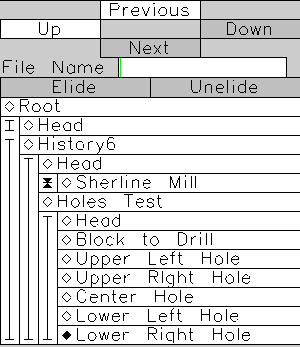
The next level down in the design tree is the history nodes. Each time you make a change to the design tree (i.e. add, change, or delete) a new history node is created to contain the changed tree. By clicking on previous history nodes, the user is able to examine the design tree in previous configurations. The history nodes stretch back to the initial condition of the tree at FunCAD start up
After the history nodes are actual design tree nodes that the user can change. The discussion of how to edit the design tree nodes is in the next section. The rest of this section describes how to operate the tree outline.
Every node is named and has a diamond next to it. The currently selected node has its diamond filled in and the remaining unselected nodes have a diamond outline. In the example above, the node "Lower Right Hole" is selected.
The selection is changed by simply selecting the clicking on the desired node with the left mouse]] button. The previous node gets deselected and the new node gets selected.
The [Up], [Down], [Previous] and [Next] buttons can be used to move the selectiong around. The [Up] button moves the selection up the tree one node closer to the root. The [Down] button moves the one node further away from the root to the node previously selected in that sub-tree. The [Previous] button moves the selection closer to the "Head" node at the current level. The [Next] button moves the selection away from the "Head" node at the current level. Finally, the [Up], [Down], [Previous] and [Next] buttons will be grayed out if they operation does not make sense at the currently selected node. For example, it makes no sense to go [Up] from the root node.
The vertical regions to the left are used to collapse and uncollapse tree sections. By clicking on a vertical region that contains a vertical line with some short horizontal black lines, the entire region is collapsed. A collapsed region is shown as to triangles separated by a short horizontal black line. In the example above, "Sherline Mill" is collapsed. To uncollapse a tree region, just click on the two triangles with a horizontal black line.
In addition to the ability to collapse and uncollapse entire sub-trees, it is possible to hide portions of a list. This is called eliding. In the example above, history nodes History1 through History5 are elided (i.e. hidden.) This is represented visually as a break in the vertical bar.
The [Elide] and [Unelide] bottons are used to control the eliding process. In order to elide a span of nodes, you first select the node in front of the span and then you select the node after the span. At this point, the [Elide] button becomes white. Upon clickin on the [Elide] button, span of nodes becomes hidden. In order to unelide a span, select two nodes, one on either side of the elided span. The [Unelide] button becomes white. Upon clicking on the [Unelide] button, the elided span becomes visible again.
The operations and parameters user interface is in the upper right as follows:
The operations are arranged vertically on the left. The parameters are arranged vertically on the right.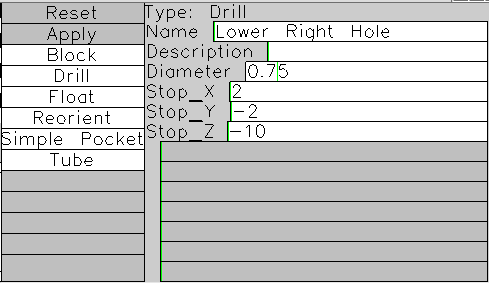
Each time a design tree node is selected, the list of valid operations is filled into the operations list. Any operations that are not immediately available are greyed out. For the example above, the available operations are [Reset], [Apply], [Block], [Drill], [Float], [Reorient], [Simple Pocket], and [Tube]. Of these operations, [Reset] and [Apply] are greyed out.
Each node has a type, name, description, and zero, one, or more parameters. For the example, above the type is "Drill", the Name iss "Lower Right Hole", and the Descripition is empty, and there are four parameters. The four parameters are "Diameter", "Stop_X", "Stop_Y", and "Stop_Z". Everything except the type can be changed by the user.
In order to change the name, description, or parameter value, you click on the value to be changed with the left mouse button and start typing. After you type the first character, all operations and the tree outline are greyed out, leaving just the [Reset] and [Apply] buttons in the white (i.e. available) state. After you have finished editing the one or more parameters and/or the name and/or description, you can click on [Apply] to cause the changes to "take" or [Reset] to return to the values prior to editing. If [Apply] is clicked, a new history node is created that contains the new design tree with the new values.
The cursor movement commands are based on EMACS as follows:
The Name and Description fields contain arbitrary strings. Most other parameters contain numbers or numeric expressions.
Numeric expressions are is standard arithmetic notation with standard operator precedence -- a*b+c*d means (a*b)+(c*d). Numbers are decimal with optional fractional parts after a decimal point -- 0, 1, 123, 1., 1.0, 3.141529, .1, .123, etc.
Besides using numbers, it is possible to use symbols to refer to other expression values in the design tree. A symbol either refers to a node name or a parameter name. When comparing names, both underscores and spaces are ignored. Thus, "StopX", "Stop_X", and "Stop X" all equivalent. The notation node_name.parameter_name is used access the value of a node parameter. Thus, "LowerRightHole.Diameter" refers to the "Diameter" parameter value for the node named "Lower Right Hole", which in this case, is 0.75.
The special symbol named "Up" causes the search to to up one level in the design tree. In the example above "Up.HolesTest.LowerRightHole.Diameter" gives the same value of 0.75. Using Up notation allows relative access to parameter value in the design tree.
There is one important special case, for a Float node, there is no need to specify the parameter_name.