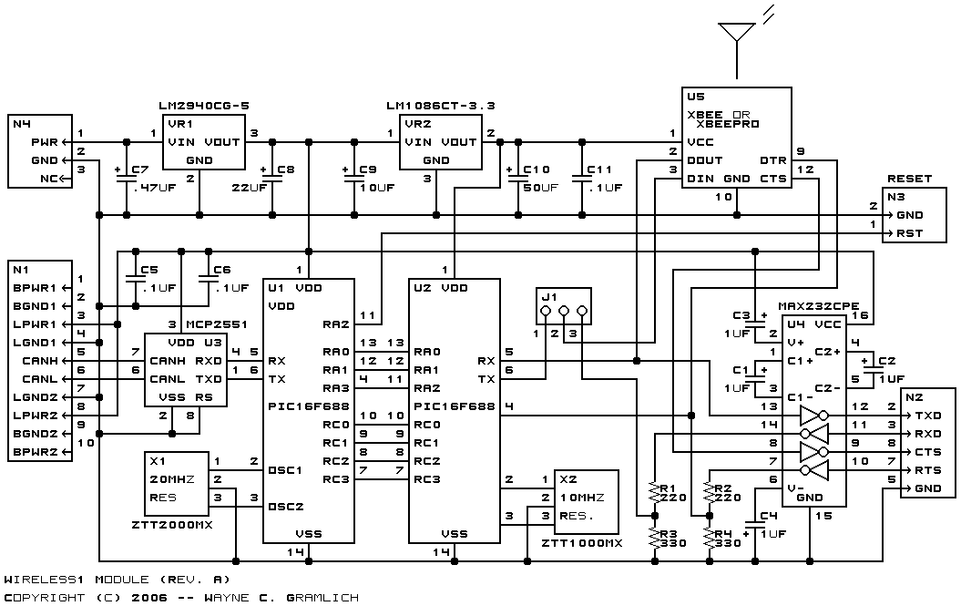
This is the revision A version of the Wireless1 module.
No programming yet.
The hardware consists of a circuit schematic and a printed circuit board.
The schematic for the Wireless1 module is shown below:
The parts list kept in a separate file -- wireless1.ptl.
The printed circuit board files are listed below:
- wireless1_back.png
- The solder side layer.
- wireless1_front.png
- The component side layer.
- wireless1_artwork.png
- The artwork layer.
- wireless1.gbl
- The RS-274X "Gerber" back (solder side) layer.
- wireless1.gtl
- The RS-274X "Gerber" top (component side) layer.
- wireless1.gal
- The RS-274X "Gerber" artwork layer.
- wireless1.gml
- The RS-274X "Gerber" mask layer.
- wireless1.drl
- The "Excellon" NC drill file.
- wireless1.tol
- The "Excellon" tool rack file.
The cable information can be found in the DB9RJ11 Module.
There are two sets of firmware available for the Wireless1 module.
The host firmware is available in the following files:
- host.ucl
- The µCL source code for the Host module.
- host.asm
- The Host module assembly code file.
- host.lst
- The Host module listing file.
- host.hex
- The µCL Wireless1 Intel® Hex file.
The bus firmware is available in the following files:
- bus.ucl
- The µCL source code for the Bus module.
- bus.asm
- The Bus module assembly code file.
- bus.lst
- The Bus module listing file.
- bus.hex
- The µCL Wireless1 Intel® Hex file.
The following fabrication issues came up: