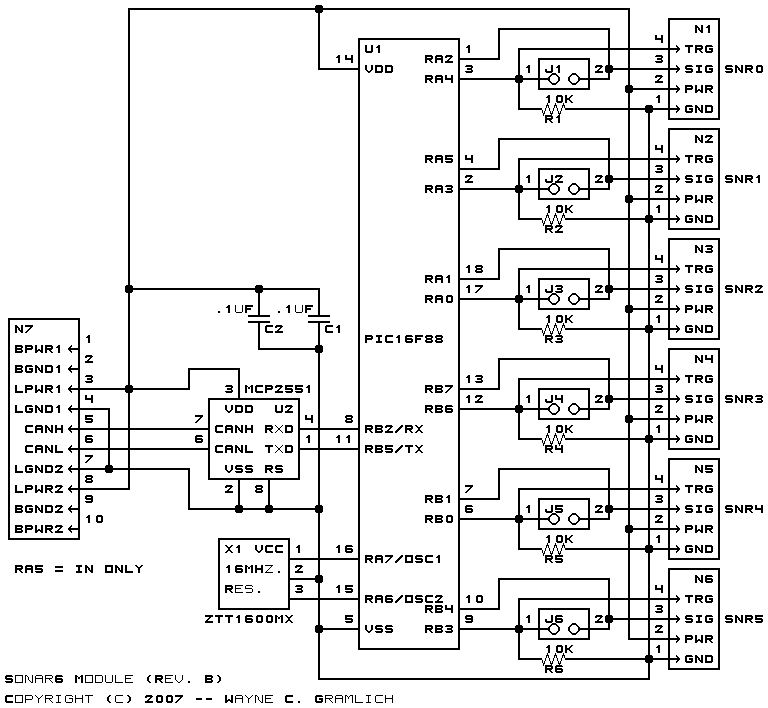
This is the revision B version of the Sonar6 module.
This controls up to 6 ultrasonic sonar devices with either a 2-wire or 1-wire interface. For the 2-wire interface, one wire is a trigger and the other returns a pulse whose width is correlated to object distance. For the 1-wire interface, these two signals are multiplexed onto one wire. The following list is a partial list of modules work with the Sonar6.
The Sonar6 module manages up to 6 sonar modules. Only one sonar module at a time is triggered. Each sonar module can be assigned a priority between 0 (highest) and 5 (lowest). The priority specifies how frequently each sonar is triggered. For example, the sonars at the front of a robot might be assigned a priority of 0 whereas the one at the rear might be assigned a priority of 5. A priority of 6 means that the sonar is triggered under program control and a priority of 7 means that the sonar is disabled.
In addition, each sonar has a distance threshold. When two consecutive distance readings on the same sonar exceed the distance threshold, the sonar priority is temporarily decremented by 1 towards 0. Thus, when rapid motion occurs near a sonar module, it will temporarily increase its trigger frequency until the motion near it calms down.
The the overall frequency at which sonars are visited is under program control. For example, the robot is motionless, the sonars can be slowed down or shut off. When the robot is moving, the scan frequency can be increased.
The programming table contains all of the programming commands. If you program in Easy-C, the file RG2_Sonar6_B.ezc contains the access routines for the module.
The hardware consists of a circuit schematic and a printed circuit board.
The parts list kept in a separate file -- sonar6.ptl.
The schematic for the Sonar6 module is shown below:
The printed circuit board files are listed below:
The following files are available:
Any fabrication errors will be listed here.