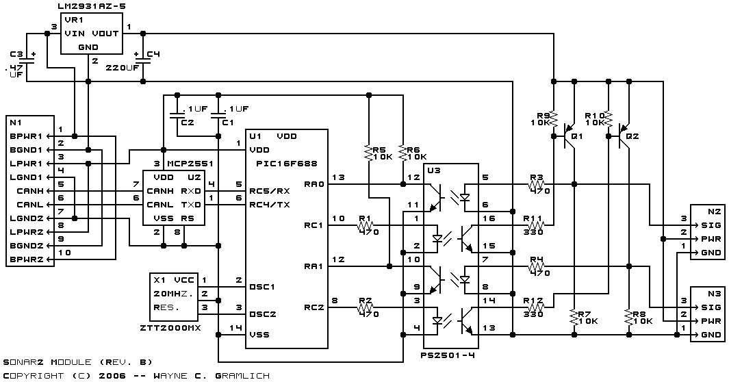
This is the revision B version of the Sonar2 module.
This is a completely optoisolated Sonar module for driving two Parallax® Ping sonar modules.
Command
NameBit Action Description 8 7 6 5 4 3 2 1 0 Centimeter_Read 0 0 0 0 0 0 s s s Send Return the distance for senosr sss as dddd dddd centimeters. 0 d d d d d d d d Receive Millimeter_Read 0 0 0 0 0 1 s s s Send Return the distance for senosr sss as dddd dddd millimeters. A return result of 1111 1111 means that the distance exceeds 254 millimeters (=10.45 inches) 0 d d d d d d d d Receive
The hardware consists of a circuit schematic and a printed circuit board.
The parts list kept in a separate file -- sonar2.ptl.
The schematic for the Sonar2 module is shown below:
The CANH and CANL signals come in from pins 5 and 6 of N1 and are routed to the CAN bus tranceiver (U2) pins 7 and 6. The resulting RX and TX signals are fed into the PIC16F688 (U1) on pins 5 and 6. The 20MHz ceramic resonator (X1) is connected to pins 2 and 3 of U1 to privide a time base.
A sonar ping is triggered by applying a voltage to to R1 to cause current to flow through the LED on pins 1 and 2 of U3. The LED photons saturate the photo transistor on pins 15 and 16 of U3. This grounds the collector (pin 16) which grounds one end of R11. This causes Q1 to turn on and saturate, bringing its collect up to +5 volts. This provides trigger signal on pin 3 on N2. When the LED current is removed, R9 pulls the base of Q1 up to +5 volts turning Q1 entirely off. Q1 needs to be entirely off before the Ping sonar module responses with its pulse.
The Ping sonar responds by sending a pulse back from pin 3 of N2. This pulse causes current to flow throw R3 and the LED on pins 5 and 6 of U3. The photons saturte the photo transistor on pins 11 and 12 of U3 and cause the collector to be pulled to ground. When the LED is off, R6 pulls the collector up to +5 volts.
The printed circuit board files are listed below:
The following files are available:
Any fabrication issues will be listed here: