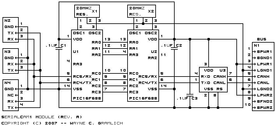
This is the revision A version of the SerialCam1 module.
The SerialCam1 module connects to a serial camera such as the CMUcam1, CMUcam2, CMUcam3, or AVRcam to the RoboBricks2 bus.
{To be done}
There are two PIC16F688 microcontrollers on the SerialCam1 module. One microctonroller is called the host processor since it is permanently attached to the host computer via the MAX232 RS-232 voltage level conveter. The other microcontroller is permanently attached the to RoboBricks2 bus and is called the bus processor. There are seven wires that are connected between the processors This section documents the data communication protocol between the two processors.
The seven wires between the two processors are labeled P6 through P0 as summarized in the table below:
Since the bus microcontroller needs to be able to generate a reset signal on N2, RA2 is used this purpose. Since RA2 is not avaiable for the interprocessor communciation, RA3 is used instead. The problem with RA3 is that it is an input only pin.
Label Host Pin Bus Pin Use Direction P6 RA2 RA3 Handshake Host to Bus P5 RA1 RA1 Handshake Bus to Host P4 RA0 RA0 Strobe Host to Bus P3 RC3 RC3 Data Host to Bus P2 RC2 RC2 Data Host to Bus P1 RC1 RC1 Data Bus to Host P0 RC0 RC0 Data Bus to Host
The host processor is always in controlling the data exchanges between the two processors. Basically data is extanged between the two processors two bits at a time. P3:2 are used to send data from the host processor to the bus processor. P1:0 are used to send data from the bus processor to the host processor. P4 is used to indicate that a command needs to be processed. P6:5 are used for handshaking between the two processors to synchronize data transfer.
The handshaking works as follows:
Currently there are only three commands that the host processor can issue and they are summarized in the table below:
Host Sends Bus Returns Description 9 8 7 6 5 4 3 2 1 0 9 8 7 6 5 4 3 2 1 0 0 s s s s s s s s s Send s ssss ssss out to the bus 1 0 e r r r r r r r r r Receive r rrrr rrrr from bus. e is 1 if no receive byte is present. 1 1 Strobe reset line on N3.
The hardware consists of a circuit schematic and a printed circuit board.
The schematic for the SerialCam1 module is shown below:
The parts list kept in a separate file -- serialcam1.ptl.
The printed circuit board files are listed below:
- serialcam1_back.png
- The solder side layer.
- serialcam1_front.png
- The component side layer.
- serialcam1_artwork.png
- The artwork layer.
- serialcam1.gbl
- The RS-274X "Gerber" back (solder side) layer.
- serialcam1.gtl
- The RS-274X "Gerber" top (component side) layer.
- serialcam1.gal
- The RS-274X "Gerber" artwork layer.
- serialcam1.gml
- The RS-274X "Gerber" mask layer.
- serialcam1.drl
- The "Excellon" NC drill file.
- serialcam1.tol
- The "Excellon" tool rack file.
The SerialCam1 uses either a 1×4; or a 1×3 .1" female to female cable. The 1x×4 cable is used for the CMUcam2 and the 1×3 cable is used for all others.
All of these cameras require a 6-9 volt source to power the camera. Since this voltage level is not available on the SerialCam1 board, the user will need to find an alternative power source.
There are two sets of firmware available for the SerialCam1 module.
The host firmware is available in the following files:
- host.ucl
- The µCL source code for the Host module.
- host.asm
- The Host module assembly code file.
- host.lst
- The Host module listing file.
- host.hex
- The µCL SerialCam1 Intel® Hex file.
The bus firmware is available in the following files:
- bus.ucl
- The µCL source code for the Bus module.
- bus.asm
- The Bus module assembly code file.
- bus.lst
- The Bus module listing file.
- bus.hex
- The µCL SerialCam1 Intel® Hex file.
Any fabrication issues will be listed here.