This is the revision B version of the Orient5 module.
The Orient5 module manages 5 channels of orientation information -- 3 axes of acceleration and 2 axes of magnetic bearing. The accelerometer is cabable of measuring platform tilt (for a non-accelerating platform) by detecting the Earth gravitational acceleration. The magnetic bearing module can detect 360 degrees of magnetic bearing.
The there axis accelerometer is based on the Parallax® Hitachi® H48C Tri-Axis Accelerometer Module. This module contains a Hitachi H48C module with has 4 analog outputs (3 axes X/Y/Z and 1 temperature) connected to a Microchip® MCP3204 4 channel 12-bit analog to digital converter.
The two axis magenetic bearing module is based on the Parallax HM55B Compass Module, which in turn is based on the Hitachi HM55B integrated circuit.
Command
NameBit Action Description 8 7 6 5 4 3 2 1 0 Compass Reset 0 0 0 0 0 0 0 0 0 Send Reset the A/D converts in the Compass module. Compass Start 0 0 0 0 0 0 0 0 1 Send Start the compass measurement: Compass Status 0 0 0 0 0 0 0 1 0 Send Return compass module status as ssss. 1100=Done, 0000=In Progress, 1111=Field overflow. 0 0 0 0 0 s s s s Receive X High Get 0 0 0 0 0 0 1 0 0 Send Return high hyte of X (signed) hhhh hhhh 0 h h h h h h h h Receive X Low Get 0 0 0 0 0 0 1 0 1 Send Return low byte of X (signed) llll llll 0 l l l l l l l l Receive Y High Get 0 0 0 0 0 0 1 1 0 Send Return high hyte of Y (signed) hhhh hhhh 0 h h h h h h h h Receive Y Low Get 0 0 0 0 0 0 1 1 1 Send Return low byte of Y (signed) llll llll 0 l l l l l l l l Receive Axis Channel High Get 0 0 0 0 0 1 0 c c Send Read 12 bits of channel cc of Axis A/D module and return the high order 4 bits as hhhh. The low 8-bits are latched. For cc, 00=X axis, 01=Y axis, 10=Z axis, 11=VRef. 0 0 0 0 0 h h h h Receive Axis Channel Low Get 0 0 0 0 0 1 1 0 0 Send Return the low 8-bits of the previous axis channel read as llll llll. 0 l l l l l l l l Receive Common
Commands0 1 1 1 1 1 1 x x Send Standard common command. See specifications for details. 0 a a a a a a a a Receive Select 1 a a a a a a a a Send Select the module with an address of aaaa aaaa. A time-out indicates that the module is not selected. (FIXME: 0xa5 is currently returned.) 0 0 0 0 0 0 0 0 0 Receive
The hardware consists of a circuit schematic and a printed circuit board.
The parts list kept in a separate file -- orient5.ptl.
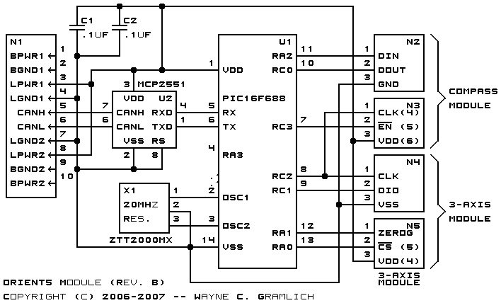
The schematic for the Orient5 module is shown below:
The printed circuit board files are listed below:
Unfortunately, it is possible to insert the two Parallax modules up-side down. Doing so will invert the power and ground to the chips and possible irreparable damage to the modules. Thus, it is very important to plug the modules into the Orient5 board correctly.
Orient the the Orient5 board such that the black 2×5 RoboBricks2 bus connector on the upper left corner. The U4 3-axis acceleration module connectors will be on the lower left and the U3 2-axis magnetometer module connectors will be on the lower right.
The following files are available:
The following fabrication issues occured:
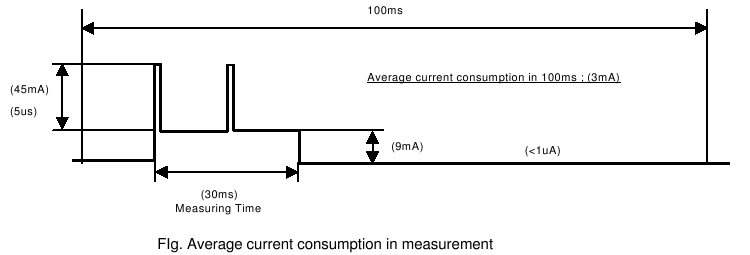
A redesign to opto isolate the chip may be necessary. Those 45mA spikes are pretty nasty looking.