This is the revision A version of the IRProximity4 module.
The IRProximity4 module works in conjunction with up to 4 IROD_Base1 boards to provide IR proximity detection in the 10-20 cm range.
The firmware for this module started out as the firmware for the Servo4 module. Thus, the commands below show the ability to talk to 4 servos. Well, the IRProximity4 only has 2 servos. Eventually, the firmware commands will be modified to only reference the two actual servos.
Command
NameAction Bit Description 8 7 6 5 4 3 2 1 0 Proximity Get Send 0 0 0 0 0 0 0 0 0 Return the 4 proximity values as pppp. xxx1=N2, xx1x=N3, x1xx=N4, and 1xxx=N5. 1=on or disconnected, and 0=off. pppp is AND'ed with mask mmmm. Receive 0 0 0 0 0 p p p p Mask Set Send 0 0 0 0 0 0 0 0 1 Set the proximity mask to mmmm. Send 0 0 0 0 0 m m m m Mask Get Send 0 0 0 0 0 0 0 1 0 Return the proximity mask as mmmm. Receive 0 0 0 0 0 m m m m Common
CommandsSend 0 1 1 1 1 1 1 x x Standard common command. See specifications for details. Receive 0 d d d d d d d d Select Send 1 a a a a a a a a Select the module with an address of aaaa aaaa. A time-out indicates that the module is not selected. Receive 0 0 0 0 0 0 0 0 0
The hardware consists of a circuit schematic and a printed circuit board.
The parts list kept in a separate file -- irproximity4.ptl.
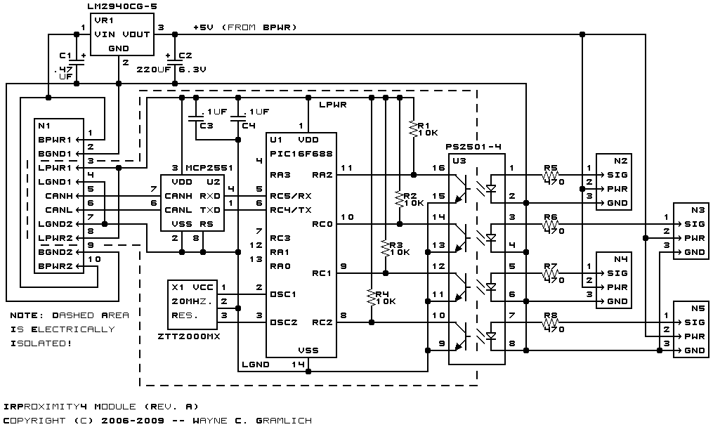
The schematic for the Irproximity4 module is shown below:
The GP2Y0D340K's used by the IROD_Base1 module have a very non-linear current draw. When the IR LED is off, they draw very little current, but when the IR LED is illiminating the target, the current goes up substantially. For this reason, the IROD_Base1 modules can not be hooked up to the logic bus (LPWR and LGND). Instead, they are hooked up to the battery power bus (BPWR and BGND) through a 1 Amp 5V low drop out voltage regulate VR1. Capacitors C1 and C2 provide the necessary regulator capacitors for VR1.
Since the RoboBricks2 bus mandates a complete electrical separation between the logic bus and the battery bus, the proximity detection signals from the IROD_Base1 modules are run through aPS2501-4 quad optoisolator. This electrical isolation is shown via the dashed line in the schematic. Resistors R5-8 are current limiting resistos for the optoisolator LED's. Resistors R1-4 are 10K pull-up resistors for the microcontroller inputs.
By the way both the schematic and circuit board were modified from the IRDistance2 (rev. C) module.
The printed circuit board files are listed below:
The following files are available:
Any fabrication issues will be listed here: