This is revision A of the
Encoder1 Module.
Encoder1 Module (Revision A)
This document is also available in
PDF format.
The Encoder1 module is a low cost quadrature
encoder that works with a paper disk of black
and white stripes.
The hardware consists of a circuit schematic and
a printed circuit board.
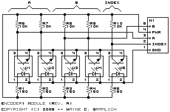
The schematic for the Encoder1 Module is shown below:

This schematic shows 5 sensors, but at most 3
should be installed. A pair of sensor should
be installed at U1 and U4 or U2 and U3. If you
need an index pulse, install a sensor at U5.
The parts list kept in a separate file --
encoder1.ptl.
The printed circuit board files are listed below:
-
encoder1_back.png
-
The solder side layer.
-
encoder1_front.png
-
The component side layer.
-
encoder1_artwork.png
-
The artwork layer.
-
encoder1.gbl
-
The RS-274X "Gerber" back (solder side) layer.
-
encoder1.gtl
-
The RS-274X "Gerber" top (component side) layer.
-
encoder1.gal
-
The RS-274X "Gerber" artwork layer.
-
encoder1.drl
-
The "Excellon" NC drill file.
-
encoder1.tol
-
The tool rack file.
The following fabrication issues came up:
-
There only needs to be one pull up and current
limit resistor per sensor. Since there is a
maximum of three sensors, only 6 resistors are
needed.
-
All of the senors need to be on the same side!
-
Think about trimming the sensors in halve.
-
The lead spacing for the sensors neads to
be increased.
-
Index sensor is pretty close to screw holes.
move it in a little.
Copyright © 2009 by
Wayne C. Gramlich.
All rights reserved.

