This is the revision B archive of my model railroad speed control project.

Model Railroad Speed Control (Rev. B)

This project is about a model trail speed control circuit designed by Juergen Kuehnel of Analog Devices. The circuit uses back-EMF from the train engine motor to determine the current speed. This circuit has the characteristic that the engine will go a constant speed irrespective of up/down grade. One nice thing about this circuit is the low speed operation.

The circuit emits a fixed width pulse and varies the height of the pulse to vary engine speed. (In-other-words, it is pulse height modulated rather than pulse width modulated.) The duty cycle of the pulses is about 90% with the 10% "off" cycle used to measure the back EMF from the motor to complete the feedback loop.

The current state of this project as of 1997-06-16 is that the circuit has been verified by Juergen Kuhnel in a protoboard. The printed circuit has been layed out and fabricated and is awaiting stuffing by Juergen. The biggest problem is that one of chips used by the circuit appears to be difficult to obtain (the CLM50.) So that portion of the circuit needs to be reworked a little.

The following diagrams exist:

Block Diagram
The block diagram of the entire circuit:

Block Diagram

Timing Circuit
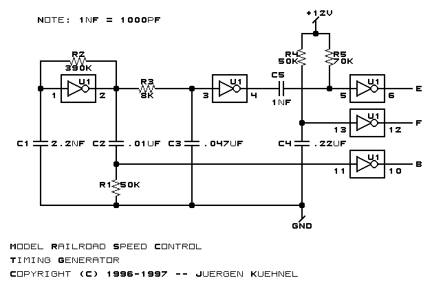
The timing pulse generator:

Timing Generator Circuit

Power Drive
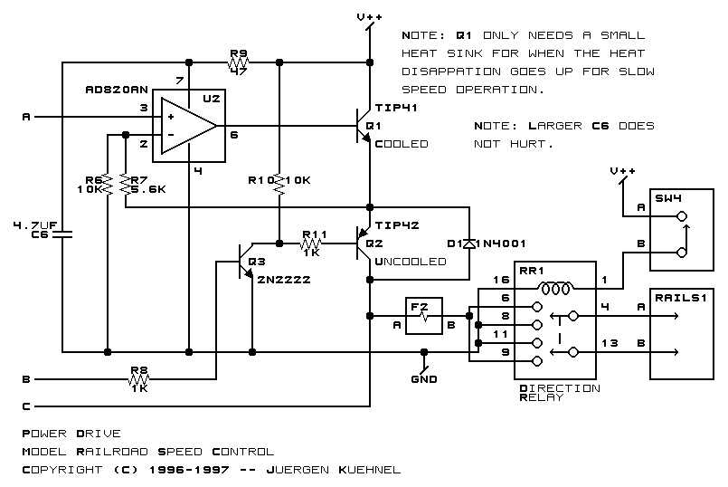
The power driver circuitry:

Power Drive Circuit

Control Amplifier
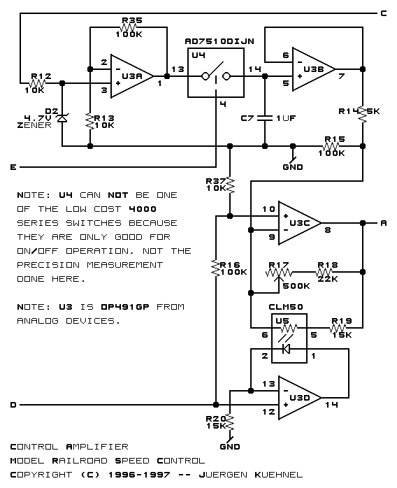
The control amplifier circuitry:

Control Amplifier Circuit

Linear Momentum
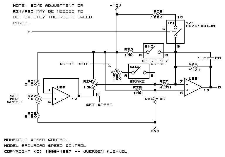
The linear momentum control:

Linear Momentum Circuit

Manual Setting
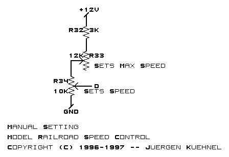
If you do not want to deal with the linear momentum control, just substitute the following manual controls:

Manual Speed Setting Circuit

Power Supply
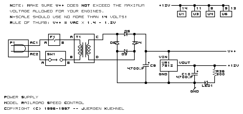
The power supply:

Power Supply Circuit

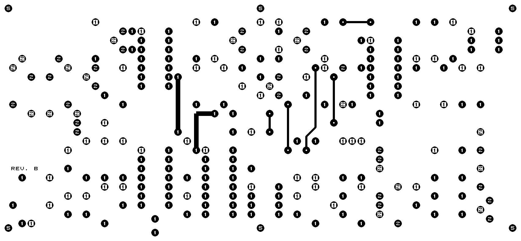
The artwork for the printed circuit board is shown below:

Solder Side
The solder side of the board:

Component Side
The component side of the board:

Artwork
The artwork for the board:

Finally, here are some links to the CAD files used to fabricate the boards:

Solder Side
The solder side file is in RS-274X format (frequently referred to as `Gerber format') and basically specifies a bunch of commands to a photoplotter to specify where the copper on the printed circuit board is to be placed.
Component Side
The component side file also in RS-274X format.
Drill File
The drill file is in so called `Excellon Format'. There is probably some RS-### number for the format, but most people just call them `Excellon drill files'.
Tool File
The tool file is just an ASCII file that specifies the mapping between T-codes in the drill file and the corresponding drill sizes.
Parts List
The parts list for the project.

The boards were fabricated by APC Circuits in Calgary, AB Canada using the files above.


Copyright (c) 1996-98 by Wayne C. Gramlich All rights reserved.