Before actually drilling any holes, it is useful
to do a rough placement of the larger pieces to
get an idea of where everything goes:
|
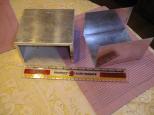
The aluminum box is Jameco 11893 and is
7.0"L × 6.2"W × × 4.6"D
in size. It comes in two "U" shaped pieces
that slide together and are attached by 4
sheet metal screws. Aluminum boxes are easy
to make holes in for various components.
|
|
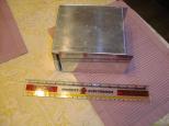
Unlike most boxes of this style, the
folded over lips for this box are
designed to go inisde the
metal piece. The picture shows how
the lip fits inside.
|
|
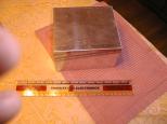
When the box is closed it looks like,
well, a box. How profound. (Yeah, the
thumbs are mine; I'm not that good of a
photographer.)
|
|
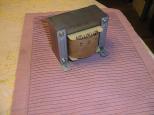
The transformer is Jameco 221410 and it
measueres 4.63"L × 3.75"W ×
4.63"H inches. It weighs in at 11.2 pounds.
It takes 117VAC in and produces 24VAC at 12A
out. Since AC is measured in RMS (Root
Mean Squared), the actual peak voltage
is actually 1.414 times larger at 33.9V,
or call it 34 volts.
|
|
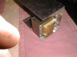
The transformer barely fits into the box.
In order to maximize space inside the box,
I wound up putting the transformer on its
side. In this orientation, the transformer
"feet" interfere with the lips of the other
box piece. Thus, when it comes time to
install the transformer, it is mounted on
top of some washers to provide some space
for the box lips to slide in. This is
lip interferance problem is annoying, but
all the other transformer orientations I
tried caused other even more serious
component interference problems. (Yeah,
that's one of my fingers.)
|
|
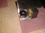
The fan is Jameco 174107 and it is the next
item that needs to put into the box. It is
placed next to the transformer towards the
"bottom" of the box. With this transformer
orientation, the fan does not have box lip
interference problems.
|
|
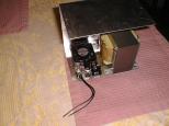
The rest of the 117VAC components are placed
on "top" of the fan. These components are
the line cord plug (Jameco 147109), the fuse
holder (Jameco 120993), and the on/off switch
(Jameco 76232). Again, there is just barely enough
room to avoid lip interference problems with
the other box piece.
|
|
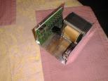
The printed circuit board (PCB) is placed on the
other side of the box. The L298's and their heat
sinks poke out and come close to touching the
transformer, but do not actually touch.
The mounting holes for the PCB are close to
the box lips, but do not actually interfere.
|
While there are going to be a number of tight fits,
everything should fit into the box.


