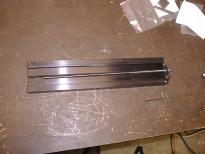
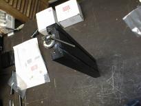

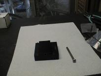

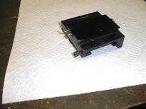



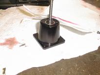
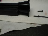
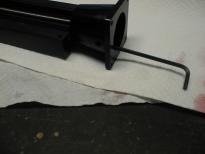


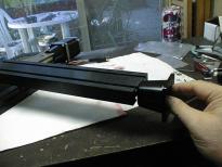
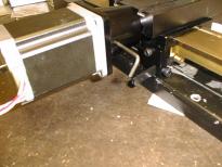
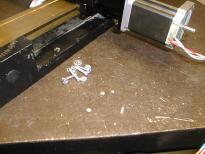
This is the X-axis conversion portion of my Sherline CNC Conversion.

|
This shows the 13" X axis after it has been removed from the manual mill with no hand wheels. |

|
The disassembly involves removing the screw that holds the thrust washer to the end of the X table. |

|
All done. The old lead screw is not needed since a the CNC conversion uses a new lead screw. |

|
My lathe is so old that it does not have any anti-backlash technology on the lathe saddle (40910). So, the next few pictures show my efforts to add an an anti-backlash nut to the old saddle. |

|
Since Sherline uses 1/4-20 lead screws for this axis, I obtained a long 2-1/2" 1/4-20 round head screww and fed it into the saddle ... |

|
... until it pokes out the other end. |

|
Next, an X axis backlash nut (50130) is threaded onto it until it is snug. The backlash lock (50150) is placed on the saddle such that it just engages the backlash nut. Sorry about the blurry picture. |

|
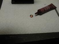
I put a little dab of lock tight on the backlash lock. |

|
The backlash lock is temporarily glued to the saddle in the correct position. Again this picture is a bit blurry. |

|
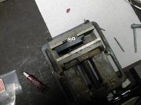
Now I put the saddle into my trusty vice. |

|
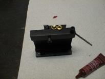
Here is the saddle getting ready to be drilled. |

|
Here is the whole mess after drilling. The flash really washed out the chips. |

|
Now the hole is tapped. You can see the family cat is really interested in this operation. As usual, after about every half turn, I back the tap up by a quarter turn to break the chips. |

|
Now the backlash lock is knocked of and cleaned. This picture shows the tapped hole. |

|
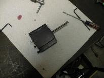
Finally the backlash lock is held down using a spare screw. Sorry about the blurry picture, for some reason, the camera decided to focus on the background. |

|
Lastly, the 2-1/2" 1/4-20 screw is removed and we are ready to move onto the next step. |

|
For some reason I am missing a bunch of pictures that show assembly of the lead screw (67024), thrust bearings (67120), preload nut (67106), and CNC coupling (67105). This picture shows the assembly step just after I have applied the locktite to the preload nut and dabbed the excess off using the edge of a paper towel. |

|
Now the CNC mount (67102) with leadscrew is positioned to be attached to 13" table. |

|
First one screw is inserted and ... |

|
... then the other. |

|
Now the X axis table is attached to the saddle. |

|
This is a bottom view of the reattached X axis table. |

|
There is not much room in the CNC mount to manually twist the CNC coupler. It takes about 10 minutes to move the X table by about 1". |

|
The stepper motor is slipped onto the the CNC mount. The flat is positioned to point towards the hole in the CNC mount. An Allen wrench is used to tighten the CNC coupler to the shaft of the CNC mount. |

|
While I do not show a picture of it, I used an electric drill attached to the shaft sticking out the other end of the stepper motor to move the X axis all the way in. Finally, the stepper motor is attached to the CNC mount using some screws and nuts. |