TEST STAND
The amateur rocket engine test stand is a structure which incorporates a
method for firmly mounting the rocket engine (preferably in a nozzle-down
attitude), a mounting for the propellant flow control needle valves, the
fuel tank and associated plumbing, and the oxygen and nitrogen cylinders
with regulators and associated plumbing. The operator's station, which
is really a part of the test stand, should be physically separated from
the test stand proper by at least 20 feet, witll a shrapnel barricade
between. The operator's station should contain the control valve extensions,
the ignition system battery and associated switches, and a mirror system
so that the operator does not directly view the operating rocket engine.
The greatest hazard in testing small rocket engines is from shrapnel
in the event of engine explosion or disintigration. Therefore, the test
stand proper should be suitably barricaded to reduce shrapnel effect
in all directions.

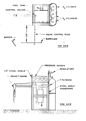
Figure 12 Test stand for small liquid-fuel rocket engines.
Figure 12 shows schematically the proper arrangement of
components for a safe rocket engine test stand. The rocket engine is
separated from the propellant flow control valves by a 1/8-inch thick
steel barricade. The engine is firmly attached to a section of steel
channel in the nozzle down position. This is the safest orientation
for a liquid-fuel rocket engine since excess fuel, in the event of an
ignition failure, simply drains out of the engine nozzle. The engine
is mounted high enough from the ground so that no flame chute or other
complicated exhaust deflector or fixture is required. The compressed
gas cylinders (one nitrogen and two oxygen) are mounted at the rear of
the test stand and are separated from the control valves compartment
by another barricade made from one-inch thick plywood. The nitrogen
and oxygen regulators are mounted on this plywood barricade above the
cylinders. In this manner, expended cylinders may he replaced with
charged cylinders without disturbing the regulators or plumbing. A
formed piece of stainless steel tubing between the oxygen manifold and
the oxygen regulator and a similar piece of tubing between the
nitrogen cylinder and its regulator are removed during cylinder
exchange, and then reconnected. Lines should always be capped when not
in use to prevent entry of dirt and other foreign objects.
The fuel tank is mounted beteeen the forward steel barricade and
the rear plywood barricade on a metal cross-piece attached to both
barricades. The tank is mounted in the vertical position with the
liquid outlet at the bottom.
The propellant flow control valves are mounted one atop the other
in a metal bracket which is attached to the forward steel barricade.
Panel mounted needle valves are recommended since they facilitate
mounting in the manner described, and do not place mounting or
operating stresses on the propellant flow tubing. Valve stem
extensions, made from 1/4-inch pipe permit operation of the control
valves from the operator's remote control station, which is located at
least twenty feet from the test stand proper. Pressure gauges for fuel
tank pressure, oxygen line pressure, cooling water exit pressure and
combustion chamber pressure are mounted in a panel which is attached
to the forward and rear barricades and which faces the operator's
remote station.
Cooling water for the rocket engine is brought into a hose
coupling attached to the stand, with semi-permanent plumbing between
the coupling and the rocket engine. Water flowing from the cooling
jacket should be directed away from the engine or can be directed
downward onto a 3-inch deep layer of coarse stones laid beneath the
roeket engine exhaust. These stones will prevent the engine exhaust
from picking up dirt and dust; the water will cool the stones and
extend their useful life. The jet of cooling water can be observed by
the operator as an indication that cooling water is actually flowing
through the engine.
The test stand proper should have a framework made from welded or
bolted steel angle. The forward steel and rear plywood barricade are
bolted to this angle framework providing rigidity and strength. Thee
test stand should be firmly attached to the surface Of the test area
either by bolting to a concrete pad or by weighing down with sand bags
or concrete weights.
