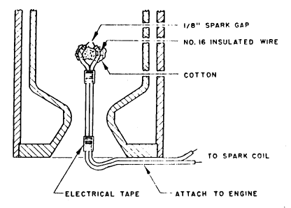
Figure 13 Hot-source igniter for small liquid fuel rocket engines using gaseous oxygen oxidizer. Ignitor is consumed during each use and must be replaced.
- The operator ascertains that the area is clear and ready for firing.
- The operator checks operation of the spark coil and then disconnects the coil from the battery for safety. The battery should be at the operator's remote station.
- The ignitor cotton is soaked in gasoline or kerosene.
- The ignitor is pushed through the nozzle into the combustion chamber and secured.
- Gas cylinder valves are opened, the fuel tank is pressurized, and all gas pressures adjusted to operating values.
- Cooling water is allowed to flow through the engine at the proper rate.
- The firing bell or horn is sounded. The spark coil is reconnected to its battery.
- The oxygen flow needle valve is opened very slightly to allow a very small flow of gaseous oxygen to pass over the ignitor and out the combustion chamber.
- The spark coil is energized. Inside the combustion chamber the cotton igitor should immediately burst into flame in the oxygen atmosphere. The operator may have difficulty ascertaining that the cotton is actually burning although small flaming bits of material may be ejected from the nozzle.
- The fuel control needle valve is now opened very slightly to allow fuel to flow into the combustion chamber. A flame should immediately appear at the nozzle exit and a low whistling sound should be heard.
- The oxygen and fuel flow rates should now be rapidly and simultaneously increased by opening the control needle valves until tie combustion chamber pressure gauge indicates that desired conditions Exist inside the chamber.
- The operator will need to judge whether more or less oxygen is required for desired O/F ratio operation. More oxygen is required if the exhaust is bright yellow or smoky. (this is an indication of unburned carbon in the exhaust); if the exhaust is transparent or bluish the oxygen flow should he decreased slightly. The correct mixture ratio is achieved when the exhaust gases are transparent (or nearly so) but the supersonic standing shocks (Mach diamonds) in the exhaust are clearly seen. Remember that as you vary the fuel and oxidizer flows you are changing not only the amount of material passing through the engine but are also affecting the temperature of the burning gases. Both of these effects will affect the combustion chamber pressure.
- The noise from the engine will he quite high, but it is a good indicator of engine operation. It may be necessary to wear ear protection because of this high noise level.
- The operator should have a timer or have someone time the engine run. It is quite safe to simply let the engine run out of liquid fuel. The gaseous nitrogen pressurizing the fuel tank then purges the fuel supply system automatically. The engine will abruptly stop operation and the operator can then turn off the flow of gaseous oxygen. If the engine is to be stopped prior to fuel depletion the fuel flow control valve should be quickly turned off, followed by opening of the nitrogen purge valve. After the engine has stopped operation (thus assuring that the nitrogen purge has forced all fuel from the engine) the gaseous oxygen valve may be turned off. The nitrogen purge valve is closed, the cylinder valves are closcd, and the fuel tank vent valve opened. The oxygen line is vented by briefly opening the oxygen flow need1e valve. Water should be allowed to flow through the engine cooling jacket for several minutes after run termination.
- In the event of engine failure, the shutdown sequence detailed in (14), above, should be followed. Always shut-off the liquid fuel first. If engine metal parts are burning, also immediately shut-off the flow of gaseous oxygen (metal will burn vigorously in an oxygen environment).
- A new ignitor will be required for each ignition attempt or firing. The ignitor assembly is partially consumed during the ignition process and residue is quickly blown from the combustion chamber upon ignition of the liquid fuel.
- Always inspect the engine and other components for damage, apparent overheating or hot spots prior to another firing.
- Some engine designs may exhibit combustion instability (chugging, chuffing, erratic combustion, etc.) at low chamber pressures or low fuel injection velocities. To avoid this problem, the operator should rapidly increase the chamber pressure after initial introduction of the liquid fuel.
Ignition and operation of small liquid-fuel rocket engines in the manner described offers the amateur a relatively safe and interesting activity. The operator will quickly discover and use many procedures to improve engine and test stand operation.
After achieving initial operation of the engine and test stand, the amateur can begin to consider methods of measuring engine thrust, determining the heat transfer to the cooling water, and noting the characteristics of the rocket engine exhaust. Photography of this exhaust is a definite challenge. As these additional features are added to the experimertal set-up, the amateur should always keep safety and safe operating procedures foremost in mind.