This is the Revision A version of the SonarSR module. The status of this project is work in progress.
This document is also available as a PDF document.
The SonarSR module is used to send and receive ultra sonic sonar pulses. Used in conjuction with the Sonar8 module, it is possible to build sophisticated sonar sensing systems for a mobile robot.
The SonarSR is designed to allow the use of relatively inexpensive ultrasound transducers available from places like Jameco (part number 136653 or 139491) for approximately $6US. With the SonarSR module it is possible (in theory) to determine distance from 3cm to 3 meters.
There are several similar reference designs that are worth mentioning. The SRF1 designed by Gerald Coe of Robot Electronics is one reference design. Another reference design is from an article entitled "Cheap Sonar" written by Keith Payea and published in the April 1997 issue of the Encoder, the newsletter of the Seattle Robotics Society; this article is based on a 1993 article by the same author entitled "Sonar on the Cheap". By the way, the link to the large version of the receiver schematic is broken. The last reference design is written by Michael Sciarra, published at http://www.chipcenter.com/". This article contains some the background material about designing with ultrasonics.
The hardware consists of a circuit schematic and a printed circuit board.
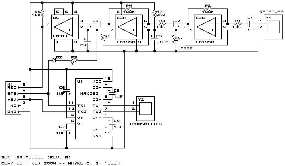
The schematic for the Sonar1 RoboBrick is shown below:
The parts list kept in a separate file -- sonarsr.ptl.
The primary design consideration for this design is to make the entire system work off of a single 5 volt power supply.
While a MAX232 is normally used to generate voltage levels for RS-232 communication, in this design the MAX232 (U1) is used to generate approximately 16 volts of drive for the ultrasonic transmitter Y1. (This clever idea came from Gerald Coe's SRF1 design.) The PIC16F628 is responsible for forming the 40KHz output pulse.
The receiver is a bit more involved. The operational amplifiers and comparator are run off a single 5 volt power supply. D1 is a LM336-2.5V voltage reference that behaves like a Zener diode. Resistor R13, biases D1 to provide a virtual `ground' of 2.5 volts.
The ultrasonic receiver Y2 feeds its signal to two 10x stages of amplification using an LM1458 (U2). The two operational amplifiers are configured as inverting 10x amplifiers (R2/R1 and R4/R3), with .1µF capacitors (C1, C2, C3) to remove any DC offset between stages.
Initially, N1-4 is idling at +5 volts which forward biases D2 and charges C4 through the current limiting resistor R8. This causes C4 to reach close to +5 volts. A ping cycle is 8 and 1/2 cycles at 40kHz. At the end of the 8 and 1/2 cycles, N1-4 is a 0 volts, back biasing D2 and allowing C4 to discharge through R6 to 2.5 volts. The discharge is a standard RC discharge rate where RC = R6 × C4. The further the object is away from the receive sensor, the smaller the peak-to-peak voltage is. The RC constant attempts to compensate for the smaller return voltages for distant objects. Whenever the positive peak voltage exceeds the voltage on C4, the U2 comparator triggers and sends a signal back to the controller board via N1-5. After receiving a response pulse, the controller board will put N1-4 back to +5 volts to start recharging C4 again for the next ping.
The printed circuit board files are listed below:
The fabrication issues are listed here.