This is the construction instructions for the
SonarDT1 (Rev. B) RoboBrick. The status of
this project is
work in progress.
SonartDT1 RoboBrick (Revision B) Construction
The instruction steps for building the Light4
(Rev. B) RoboBrick are listed below:
-
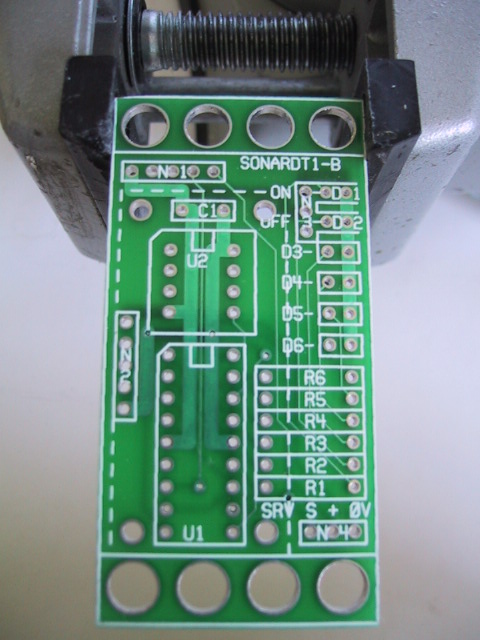
Take the board and orient it vertically.
By convention the upper edge is north,
the lower edge is south, the left edge
is west, and the right edge is east.
Orient the board so that N1 is in the
north west corner.
[Step1]
-
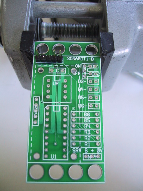
Take a 1×5 male header and using
some diagonal cutters, snip off pin 2 using
the diagram below:
Pin 2 is the pin marked with an `X'. Insert
the header into N1 with pin 1 to the west.
Turn the board over and solder one pin.
If the header is not pointing straight up,
re-heat the pin and reposition the header
until it is straight up. Now solder the
remaining 4 pins.
[Step2]
-
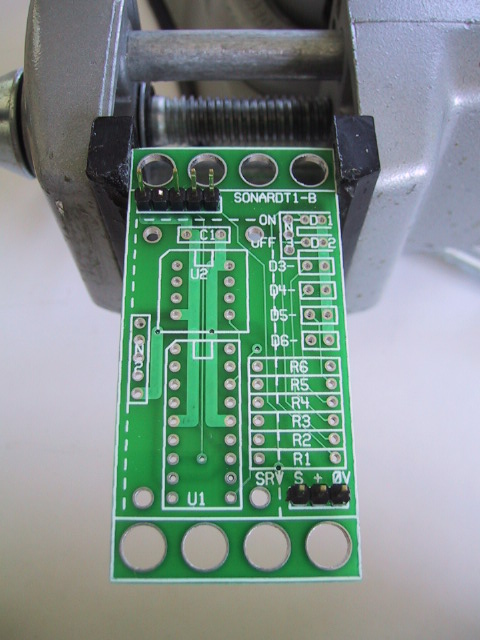
Find a 1×3 male header, insert it into
N4, solder one pin, verify that it is still
vertical, re-heat and reposition if necessary,
and solder the remaining 2 pins in.
[Step3]
-
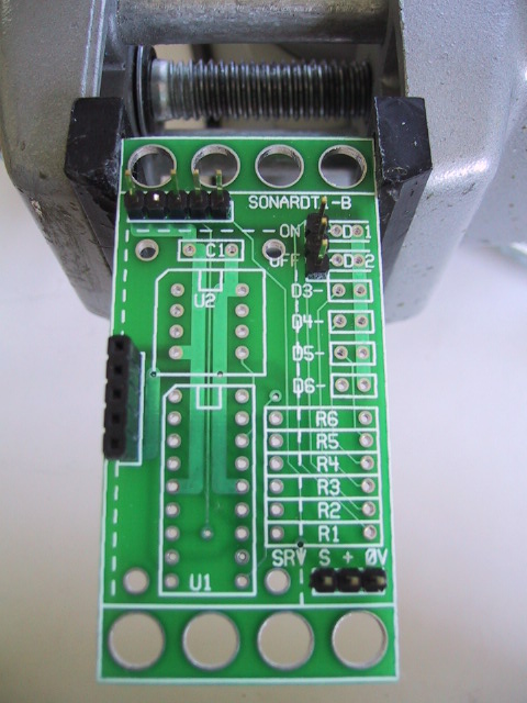
Find a 1×3 male header, insert it into
N3 in the north east corner and repeat the
steps from the previous instruction. Note that
the legend for N3 can be a little hard to read
some times.
[Step4]
-
Find the 1×5 female header, insert it into
N2, solder one pin, verify that it is still
vertical, re-heat and reposition if necessary,
and solder the remaining 4 pins in.
[Step5]
-
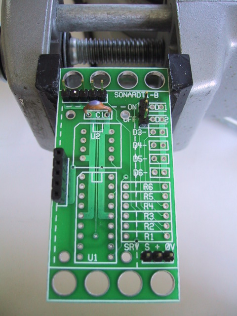
Find a 10pF capacitor and insert it into C1.
Spread the leads a little so it will not
fall out. Turn the board over and solder
one lead. Turn the board over again and
verify that the capacitor is still positioned
vertically. If not, re-heat the lead you
just soldered an reposition the capacitor.
Now solder the remaining lead. Snip off
the excess capacitor leads.
[Step6]
-
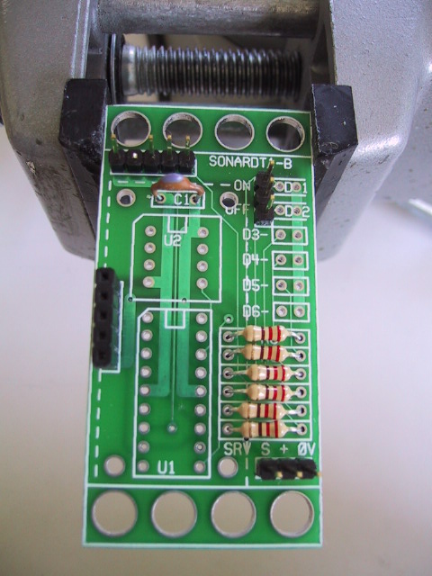
Find a 220 Ohm resistor (Red Red Brown).
Bend both leads 90 degrees so that the
resistor comfortably fits into R1. Just for
consistency, place the red band to the east.
(Resistors are symmetric, so there is no
damage done if you install the resistor
with the red band west.) Turn the board over,
and spread the leads a little to keep it from
coming out. Solder one lead. Now turn it over
to verify that the position is acceptable.
If not, re-heat the lead you just soldered and
get it positioned to your liking. Solder in
the remaining lead. Snip off the excess leads
sticking out the back.
[Step7]
-
Repeat the preceding instruction with five
more of the same resistors and insert them
into R2 through R6. Solder them as in
the preceding instruction.
[Step8]
-
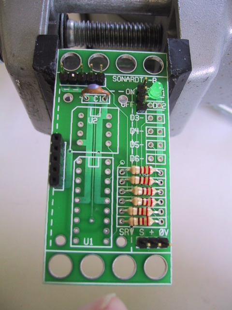
Find a small green LED. The LED has one lead
that is slightly longer than the other. The
longer lead is the positive (`+') lead and the
shorter lead is the negative (`-') lead.
Insert the first LED into D1 with the positive
lead on the east, and the negative lead on the
west. It is important that you get the LED
oriented correctly; otherwise the LED's will
not work. Solder one lead, verify that the LED
is flat against the board, re-heat and reposition
if necessary, and solder the remaining lead.
[Step9]
-
Using the previous instruction, install the
remaining 5 green LED's into D2 through D6.
You may find that the LED's are just a tiny
bit too wide. If so, just use your diagonal
cutters to snip off the plastic edge from both
sides of each diode.
[Step10]
-
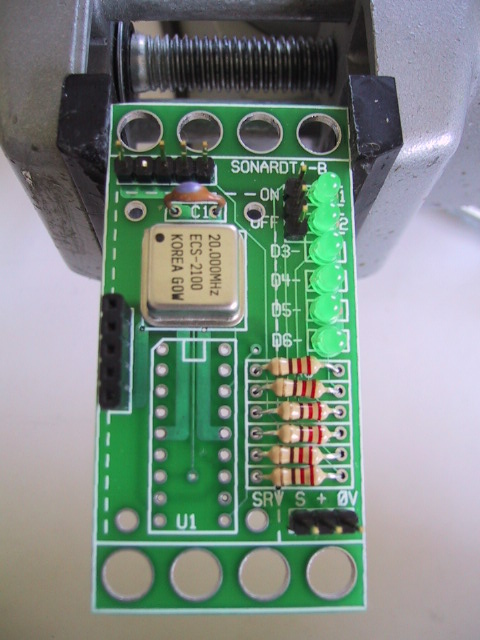
Install the crystal oscillator into U2 with
pin 1 in the north west. Pin 1 is the square
corner or the corner with the dot next to it.
If the dot is missing or not particularly close
to a corner, use the square corner to find
pin 1 instead. Spread the leads to hold the
crystal in. Solder one lead, verify position,
solder the remaining leads, and snip off the
excess.
[Step11]
-
Install the 18-pin DIP socket into U1. Place
pin 1 to the north west. The sockets typically
have a notch on the end that has pin 1. In the
picture, the notch is highlighted with some
white marker. If the socket is installed the
upside down, no harm occurs.
[Step12]
-
Find the pre-programmed PIC16F628 and insert
it into the socket at U1 with pin 1 pointing
up.
[{Step 13 picture is missing}]
-
For this next step we are going to install
a male header on the SRF04. The two metal
cans on the SRF04 are the ultrasonic
transducers for the SRF04; they are on the
front side of the SRF04. The male
header will go on the back side
of the SRF04, pointing away from
the two metal cans. {We need a picture here}.
-
Find the 1×5 male header and snip off
pin 2 as shown in the diagram below:
Pin 2 is marked with an `X'.
Orient the SRF04 so that the ultrasonic
transducers are pointing down and so that
the five holes are on the north. Insert the
1×5header into the 5 holes with pin
1 to the west. Solder one pin, verify that
it is vertical, re-heat and reposition if
necessary, and solder in the remaining 4 pins.
[Step14]
-
{Install the two screws (what size).}
[{picture missing}]
-
Insert the SRF04 into N2.
[{picture missing}]
-
Insert the shorting block onto N3 on the north
two pins.
[{picture missing}]
The assembly of the SonarDT1 (Rev. B) RoboBrick is
complete.
SonartDT1 RoboBrick (Revision B) Check Out
Perform the following steps to test out the SonarDT1
RoboBrick:
-
Make sure that both the PIC16F628 (U1)
and the 20MHz oscillator (U2) are not
plugged into their respective sockets.
-
The pinouts for the connectors are listed
below:
-
N1 - RoboBrick Cable Connector
-
| N1 |
| 1 |
2 |
3 |
4 |
5 |
| GND |
n/c |
+5V |
SIN |
SOUT |
-
N2 - SRF04 Connector
-
| N2 |
| 1 |
GND |
| 2 |
n/c |
| 3 |
TRIG |
| 4 |
ECHO |
| 5 |
+5V |
-
N3 - LED's Enable Header
-
-
N4 - Servo Connector
-
-
The pin-outs for the two sockets are listed
below:
-
U1 -- PIC16F628
-
| U1 |
| 1 |
RA2 |
RA1 |
18 |
| 2 |
RA3 |
RA0 |
17 |
| 3 |
RA4 |
OSC1 |
16 |
| 4 |
RA5 |
|
15 |
| 5 |
GND |
+5V |
14 |
| 6 |
|
|
13 |
| 7 |
RB1 |
|
12 |
| 8 |
RB2 |
|
11 |
| 9 |
TB3 |
|
10 |
-
U2 - 20MHz Oscillator
-
| U2 |
| 1 |
|
+5V |
8 |
| 2 |
|
|
7 |
| 3 |
|
|
6 |
| 4 |
GND |
20MHz |
5 |
-
Using a continuity checker (i.e. an ohm meter),
verify that N1-1, N2-1, N4-3, U1-5, and U2-4
are all connected. (N1-1 means connector N1,
pin 1.)
-
Using a continuity checker, verify that N1-3,
N2-5, N3-3, N4-2, U1-14, and U2-8 are all
connected together. When testing N2, you will
have to stick a wire into the appropriate hole
of the female socket to get electrical
connectivity out.
-
Using a continuity checker, verify that N1-1
and N1-3 are not connected
together (i.e. there is no power supply short.
-
Apply 5 volts to the SonarDT1 RoboBrick.
This is done easily by connecting a standard
RoboBrick cable from a master RoboBrick such
as the
BS2Hub8 RoboBrick or the
PIC876Hub10 RoboBrick.
-
Using a volt meter, verify that there is 5 volts
from U1-5 (GND) to U1-14 (+5V).
These are the upper two pins.
-
Put a shorting block across pins 2 and 3 of N3.
This is the upper two pins.
-
Using a wire that is bare on both ends, plug
one end into U1-5. Now tap pins tap pins 17,
18, 1, 2, 3, and 4 of U1 to verify that the
LED's light up one by one. If they do not
light up, you've got the LED's installed
backwards or you installed the shorting block
on the wrong pins.
-
Turn the power off. Plug the PIC16F628 into
U1. Plug the SRF04 into N2. Apply power.
The LED's should start to show the distance
being read from the SRF04. Using your hand
in front of the SRF04, move your hand forward
and backwards to watch the LED's count in
binary.
You are done.
Copyright (c) 2002 by
Wayne C. Gramlich.
All rights reserved.