This is the Revision D version of the
Sonar8 module. The status of this project is
work in progress.
Sonar8 Module (Revision D)
This document is also available as a
PDF document.
The Sonar8 module is used to send and receive ultra
sonic sonar pulses using the
Robot Electronics
SRF04 sonar ranging module. Up to 8 SRF04's can
be controlled by this module.
There is no programming specification for the Sonar1
RoboBrick yet.
The hardware consists of a circuit schematic and
a printed circuit board.
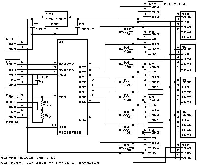
The schematic for the Sonar1 RoboBrick is shown below:

The parts list kept in a separate file --
sonar8.ptl.
The printed circuit board files are listed below:
-
sonar8_back.png
-
The solder side layer.
-
sonar8_front.png
-
The component side layer.
-
sonar8_artwork.png
-
The artwork layer.
-
sonar8.gbl
-
The RS-274X "Gerber" back (solder side) layer.
-
sonar8.gtl
-
The RS-274X "Gerber" top (component side) layer.
-
sonar8.gal
-
The RS-274X "Gerber" artwork layer.
-
sonar8.drl
-
The "Excellon" NC drill file.
-
sonar8.tol
-
The "Excellon" tool rack file.
The Sonar8 software is available as one of:
-
sonar8.ucl
-
The µCL source file.
-
sonar8.asm
-
The resulting human readable PIC assembly file.
-
sonar8.lst
-
The resulting human readable PIC listing file.
-
sonar8.hex
-
The resulting Intel® Hex file
that can be fed into a PIC12C5xx programmer.
The following issues came up during fabrication:
-
Connector N11 does not interfere with
the Ping sensor plugged into N12. Thus, N11 can
be moved to the right edge of the board.
-
The capacitor C3 is a problem in its current
location. First, it interferes with the
PIC16F688 in socket U1. Second, it interferes
with the Ping when it is plugged into N12.
Third, there is currently only room for an
8mm round capacitor.
-
Seriously consider making R3-R10 vertical,
to allow U1 to be placed into a veritical
mode. This should clear up space for the
power supply and allow a larger C3 capacitor.
Copyright (c) 2001-2002 by
Wayne C. Gramlich.
All rights reserved.
