This is the Revision A version of the Sonar1 RoboBrick. The status of this project is work in progress.
This document is also available as a PDF document.
The Sonar1 RoboBrick is a module that is designed to allow the use of relatively inexpensive ultrasound transducers available from places like Jameco (part number 136653 or 139491) for approximately $6US. With the Sonar1 Robobrick, it is possible (in theory) to determine distance from 3cm to 3 meters. Like the Laser1 RoboBrick, the Sonar1 has the ability to drive a servo to sweep the sonar sensors back and forth.
There are several similar reference designs that are worth mentioning. The SRF1 designed by Gerald Coe of Robot Electronics is one reference design. Another reference design is from an article entitled "Cheap Sonar" written by Keith Payea and published in the April 1997 issue of the Encoder, the newsletter of the Seattle Robotics Society; this article is based on a 1993 article by the same author entitled "Sonar on the Cheap". By the way, the link to the large version of the receiver schematic is broken. The last reference design is written by Michael Sciarra, published at http://www.chipcenter.com/". This article contains some the background material about designing with ultrasonics.
There is no programming specification for the Sonar1 RoboBrick yet.
The hardware consists of a circuit schematic and a printed circuit board.
The schematic for the Sonar1 RoboBrick is shown below:
The parts list kept in a separate file -- sonar1.ptl.
The primary design consideration for this design is to make the entire system work off of a single 5 volt power supply.
While a MAX232 is normally used to generate voltage levels for RS-232 communication, in this design the MAX232 (U2) is used to generate approximately 16 volts of drive for the ultrasonic transmitter Y1. (This clever idea came from Gerald Coe's SRF1 design.) The PIC16F628 is responsible for forming the 40KHz output pulse.
The receiver is a bit more involved. The operational amplifiers and comparator are run off a single 5 volt power supply. D1 is a LM336-2.5V voltage reference that behaves like a Zener diode. Resistor R13, biases D1 to provide a virtual `ground' of 2.5 volts.
The ultrasonic receiver Y2 feeds its signal to two 10x stages of amplification using an LM1458 (U3). The two operational amplifiers are configured as inverting 10x amplifiers (R2/R1 and R4/R3), with .1µF capacitors (C1, C2, C3) to remove any DC offset between stages.
The comparator design is basically taken from Keith Payea's design. The detector is set up to notice when it receives a signal that whose magnitude is exceeds 5mV to 2V depending upon time. Due to the geometry of the circuit, detection occurs when the voltage is `below' the virtual ground. A single LM311 (U4) is hooked up with a 1MOhm resistor (R7) to provide some positive feedback for a little hystersis. Capacitor C4 is just to provide a little power supply stability for the U4.
At the end of `ping' cycle, capacitor C5 is fully charged up to pretty close to the 2.5 virtual ground. The `end' trigger threshold is set by R8 and R9 to be approximately 5mV (R9/(R8+R9) × 2.5V ~= 5mV.) When the microcontroller (U1) turns the transistor (Q1) on, it discharges C5. This sets the `start' trigger threshold to R10/R9. With R10 set to the 12.5K (the middle of its 25K range), the threshold is R10/(R9+R10) × 2.5V (=1.1V.) Decreasing R10 will increase the threshold voltage. R10 in conjunction with R11 control how fast capacitory C5 charges and reverts to the `end' trigger voltage.
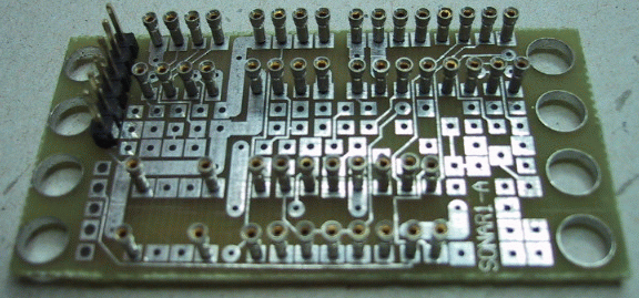
The printed circuit board files are listed below:
No software for the sonar1 has ever been written.
The follwing fabrication issues came up:
