This is the Revision C version of the
Serial1 Module. The status of this project is
work in progress.
Serial1 Module (Revision A)
This document is also available as a
PDF document.
The Serial1 Module is a Module that
connects a master Module to a computer
via a stanadard 4-wire telephone cord extension.
The hardware consists of a circuit schematic and
a printed circuit board.
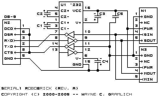
The schematic for the Serial1 Module is
shown below:
The parts list kept in a separate file --
serial1.ptl.
The printed circuit board files are listed below:
-
serial1_back.png
-
The solder side layer is shown below:
-
serial1_front.png
-
The component side layer is shown below:
-
serial1_artwork.png
-
The optional artwork layer is shown below:
-
serial1.gbl
-
The RS-274X "Gerber" back (solder side) layer.
-
serial1.gtl
-
The RS-274X "Gerber" top (component side) layer.
-
serial1.gal
-
The RS-274X "Gerber" artwork layer.
-
serial1.drl
-
The "Excellon" NC drill file.
-
serial1.tol
-
The "Excellon" NC drill rack file.
The following fabrication issues need to be addressed:
-
Use electrolytic capacitors instead of
tantalum capacitors.
-
Perhaps move the connector in some.
Copyright (c) 2000-2005 by
Wayne C. Gramlich.
All rights reserved.