This is the Revision A version of the ScanPanel Module. The status of this project is work in progress.
This document is also available as a PDF document.
The ScanPanel module is meant to be attached to a standard servo arm to provide a convenient location to attach other modules for scanning purposes. Currently, this module provides the specialized connections between Sense3 and the ScanBase.
Servo arms typically have 3 or 4 holes in a row on each arm. These holes are typically spaced 3 millimeters apart. The initial distance from the center of the servo arm is not standardized. In order to accomadate as many different servo arms as possible, the ScanPanel modules has three sets of holes as shown in the table below:
Using a cross style horn, the holes should line up one of the hole sets above.
Angles (degrees) Hole distances 30, 210 6, 9, 12, 15 90, 270 7, 10, 13, 16 150, 330 8, 11, 14, 17
...
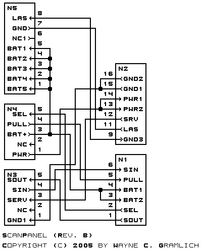
The schematic is shown below:
The parts list is kept in a separate file.
The printed circuit files are listed below:
Any fabrication issues will be listed here.