This is the revision B version of the MicroBrain8 module. The status of this project is finished.
This document is also available as a PDF document.
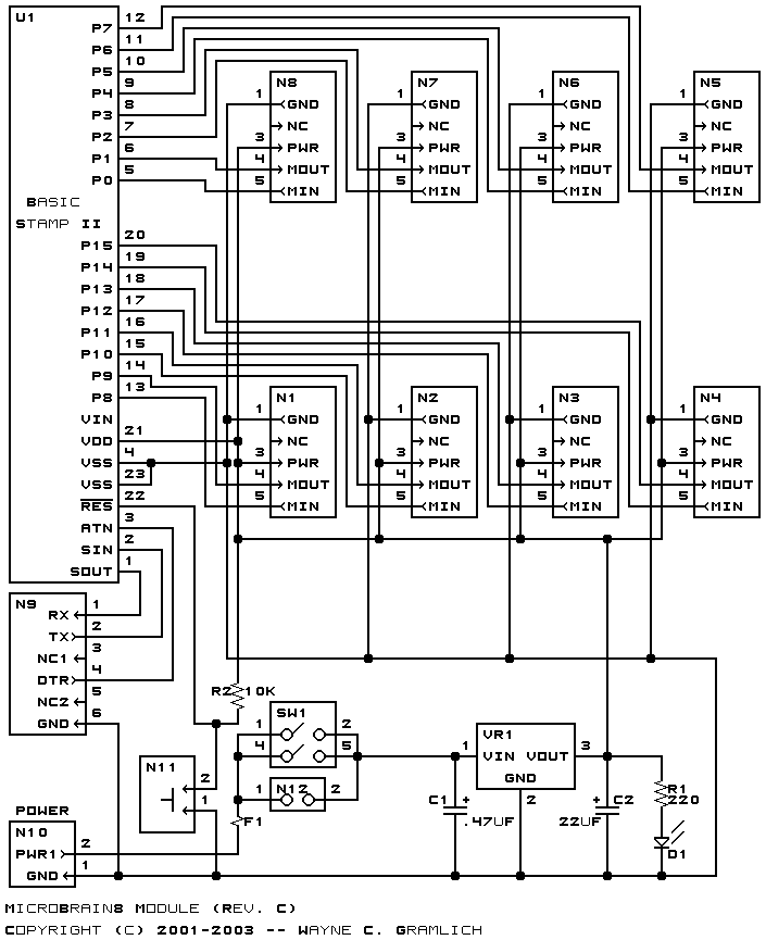
The MicroBrain8 module is a controller module that can control up to 8 sensor or actuator modules. It is controlled by any microcontroller that is pin compatible with the Parallax a Basic Stamp 2® It has two terminals that can be connect to a battery between 6 and 9 volts. It has an on board 5 volt voltage regulator to provide power to the other sensor and actuator modules. The is a connector that can be connected to a DB9 connector and used to communicate with a controlling PC via RS-232 voltage levels.
The MicroBrain11 works with any processor that is pin compatible with the Basic Stamp 2 from Parallax. This includes several products from Parallax (e.g. Basic Stamp 2, Basic Stamp2SX, Javalin) and some products from other companies such as (e.g. OOPIC-C from Savage Innovations, etc.)
The required pin-outs from the chip are:
Pin Label Description Pin Label Description 1 SOUT Serial Out 24 VIN Unregulated > 6 Volts 2 SIN Serial In 23 VSS Ground (0 Volts) 3 ATN Attention 22 RES# Reset 4 VSS Ground (0 Volts) 21 VDD Regulated +5 Volts 5 P0 Data Pin 0 20 P15 Data Pin 15 6 P1 Data Pin 1 19 P14 Data Pin 14 7 P2 Data Pin 2 18 P13 Data Pin 13 8 P3 Data Pin 3 17 P12 Data Pin 12 9 P4 Data Pin 4 16 P11 Data Pin 11 10 P5 Data Pin 5 15 P10 Data Pin 10 11 P6 Data Pin 6 14 P9 Data Pin 9 12 P7 Data Pin 7 13 P8 Data Pin 8
All 16 pins from the microcontroller processor are brought out to the connectors N1-N8. You are free to do whatever you want with these pins; after all, you own the board. You are not required to exclusively talk to RoboBRiX modules.
Having said that, we expect that most people will want to use the MicroBrain8 to operate other RoboBRiX modules. The pins from the processor chip are routed to connectors N1 through N8 in pairs as shown in the table below:
Notice that they are always organized in pairs of the form Pn=Output and Pn+1=Input. The same information, but presented from the point of view of the connector is listed below:
Pin Out Pin In Connector (Pin 4) Connector (Pin 5) P0 P1 N8 N8 P2 P3 N7 N7 P4 P5 N6 N6 P6 P7 N5 N5 P8 P9 N1 N1 P10 P11 N2 N2 P12 P13 N3 N3 P14 P15 N4 N4
Connector Input Output N1 (Top) P8 P9 N2 P10 P11 N3 P12 P13 N4 P14 P15 N5 P6 P7 N6 P4 P5 N7 P2 P3 N8 (Bottom) P0 P1
We may eventually put a few examples of programming the MicroBrain8 here. Basically, it is programmed using the Parallax Basic for the Basic Stamp 2.
    ' Even numbered pins inputs and odd number pins are outputs.
    ' (Remember for the BS2, 1=output and 0=input.)
    dirs = $aaaa

    ' Set all outputs to high:
    high 1
    high 3
    high 5
    high 7
    high 9
    high 11
    high 13
    high 15

    ' To copy a Switch8-B (on N2) to LED10-B (on N1):
    switches var byte
    loop:
	' Send command 0 (Read switches) to Switch8-B:
	serout 11, 396, [0]
	' Receive the switch readings from Switch8-B:
	serin 10, 396, [switches]
	' Send switch values to LED10-B:
	serout 9, 396, [switches]
	goto loop
The hardware consists of a circuit schematic and a printed circuit board.
The schematic for the MicroBrain8 RoboBrick is shown below:
The parts list kept in a separate file -- microbrain8.ptl.
The printed circuit board files are listed below:
The construction instructions are kept in a separate file document to be a little more printer friendly.
The software for the MicroBrain8 is developed by the user.
Any fabrication issues that come up will be listed here.