This is the construction instructions for the
InOut10 (rev. C) RoboBrick. The status of this project is
work in progress.
InOut10 RoboBrick (Revision C) Construction
The instruction steps for building the InOut10
(Rev. C) RoboBrick are listed below:
-
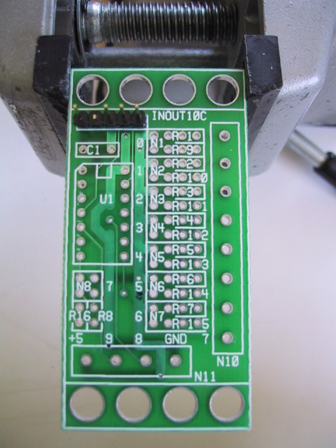
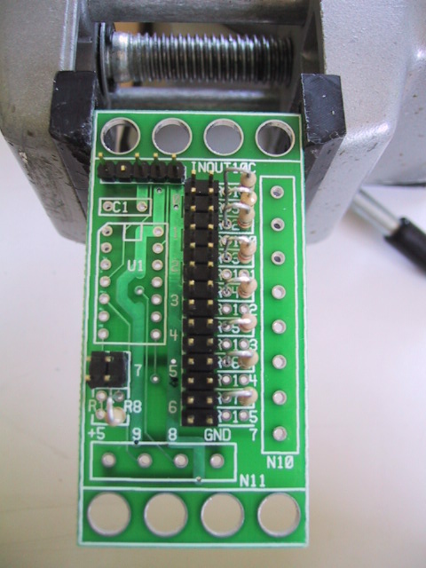
Orient the board vertically. By convention
the upper edge is north, the lower edge is
south, the left edge is west, and the
right edge is east. Orient the board so that
N9 is in the north west corner.
[step1.jpg]
-
Take a 1×5 male header and using
some diagonal cutters, snip off pin 2 using
the diagram below:
Pin 2 is the pin marked with an `X'.
Install the 1×5 male header into N9
with pin 1 to the west. First, solder only
one pin and verify that the connector is
pointing straight up. If not, use the
soldering iron to melt solder around the
pin you just solder and reposition the
header so that it is pointing straight up.
When you are happy with the position,
solder in the remaining 4 pins.
[step2.jpg]
-
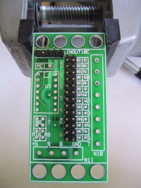
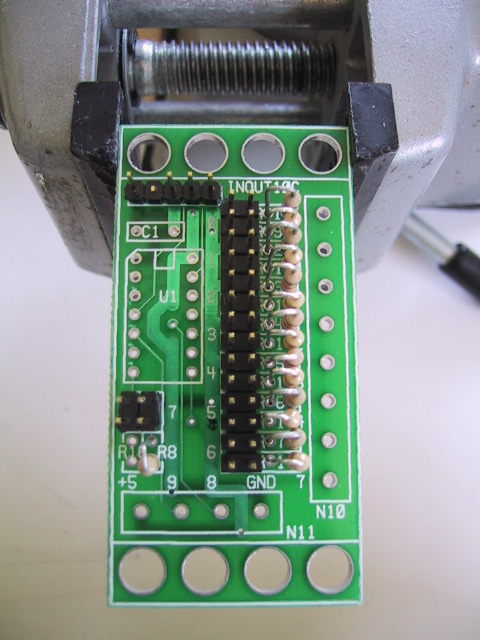
Take a 2×14 male header, orient it so
that it is vertical, and insert it into N1
through N7. As in the previous instruction,
solder 1 pin, verify that it is completely
vertical, and solder the remaining 13 pins in.
[step3.jpg]
-
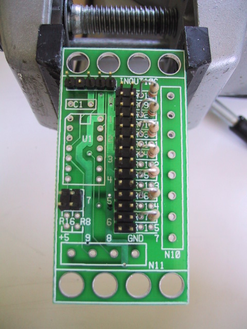
Take a 2×2 male header, insert it into
N8, solder one pin, verify position, and solder
in the remaining 3 pins.
[step4.jpg]
-
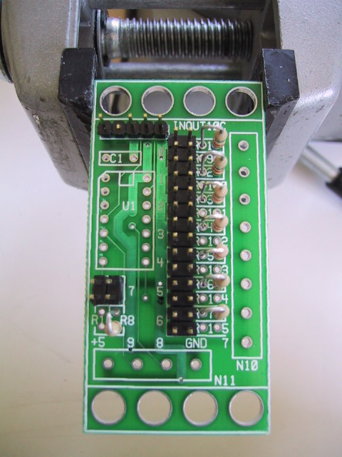
Find a 10K resistor (Brown Black Orange).
Take the lead that is closest to the brown
band and bend it around 180 degrees. Insert
the resistor into R1 with the resistor to
the east and the bend lead to the west.
Turn the board over, and spread the leads
a little to keep it from coming out. Solder
one lead. Now turn it over to verify that
the position is acceptable. If not, re-heat
the lead you just soldered and get it positioned
to your liking. Solder in the remaining lead.
Snip off the excess leads sticking out the back.
[step5.jpg]
-
Repeat the preceding instruction with 6 more
10K resistors and insert them into R2 through
R7.
[step6.jpg]
-
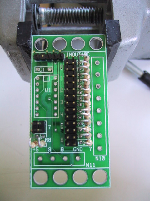
Install the last 10K resistor in R8. The
resistor base should go into the south
hole and the the bent lead should go into
the north hole.
[step7.jpg]
-
Next, find a 220 Ohm resistor (Red, Red, Brown).
Bend the lead closes to the red band over 180
degrees. Install the resistor into R9 with
the resistor to the west and the bent lead
to the east (i.e. the opposite of R1.)
Spread the leads, solder 1 lead, verify position,
solder the remaining lead, and snip of the
excess leads.
[step8.jpg]
-
Find 6 more 220 Ohm resistors (Red, Red, Brown)
and install them into R9 through R15 using the
same process as the previous step.
[step9.jpg]
-
Find the last 220 Ohm resistor (Red, Red, Brown)
and install it into R16 using the same process
as the previous two steps.
[step10.jpg]
-
Find the 4-terminal terminal strip and insert
it into N11. If all you can find is some 2-terminal
strips, a 4-terminal strip can be assembled from
two 2-terminal strip by sliding them together.
Make sure that the wire holes point towards the
south. Solder in 1 pin, verify position, and
solder the remaining pins.
[step11.jpg]
-
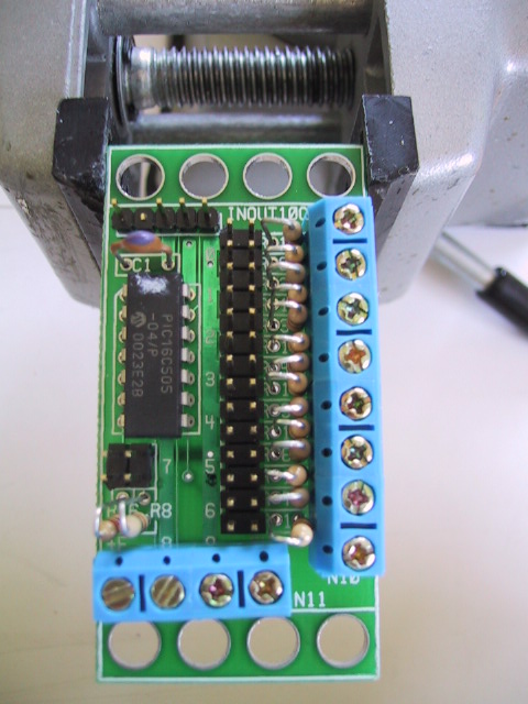
Find the 8-terminal terminal strip and insert
it into N10. If all you can find is some 2-terminal
strips, an 8-terminal strip can be assembled from
four 2-terminal strip by sliding them together.
Make sure that the wire holes point towards the
east. Solder in 1 pin, verify position, and
solder in the remaining pin.
[step12.jpg]
-
Find the 10pF capacitor and install it at C1.
Snip off the excess leads.
[step13.jpg]
-
Find the pre-programmed PIC16C509 and insert
it into U1 with pin 1 pointing up. Solder
in 1 pin, verify position, and solder in
the remaining pins. The picture marks the
notch in the chip with a little white marker.
[step14.jpg]
-
Install the shorting blocks on N1 through N16.
[{Missing Picture}]
The assembly of the InOut10 (Rev. C) RoboBrick is
complete.
Copyright (c) 2002 by
Wayne C. Gramlich.
All rights reserved.