This is the Revision A verion of the
Hub8 RoboBrick. The status of this project is
that it has been
replaced by the
PIC876Hub10 RoboBrick.
Hub8 Robobrick (Revision A)
This document is also available as a
PDF document.
The Hub8 RoboBrick is the RoboBrick that
controls the mobile robot. The Hub8 is
based on the
MicroChip® PIC16F874
microcontroller. Eventually, over time, other
master RoboBricks based on other processors
are likely to be developed.
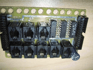
A picture of a Hub8-A RoboBrick is shown below:

The hardware consists of a circuit schematics and
a printed circuit board.
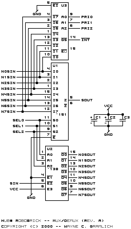
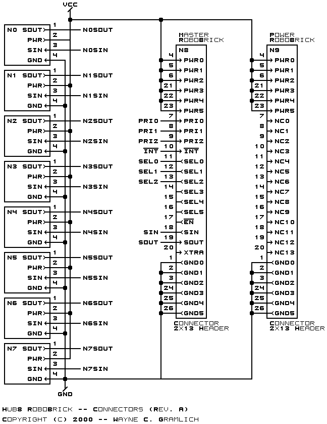
The schematic for the Hub8 RoboBrick is
shown below:


The parts list kept in a separate file --
hub8.ptl.
-
hub8_back.png
-
The solder side layer.
-
hub8_front.png
-
The component side layer.
-
hub8_artwork.png
-
The artwork layer.
-
hub8.gbl
-
The RS-274X "Gerber" back (solder side) layer.
-
hub8.gtl
-
The RS-274X "Gerber" top (component side) layer.
-
hub8.gal
-
The RS-274X "Gerber" artwork layer.
-
hub8.drl
-
The "Excellon" NC drill file.
-
hub8.tol
-
The "Excellon" NC drill rack file.
The following issues came up:
-
The crimping tool for 4-wire modular plugs is
difficult to obtain. Upgrade to 6-wire plugs.
-
Capacitor C1 is too close to N3. Move it
left .05 inches.
-
The signal trace under N1 shorts with the power
trace. Move it.
-
Try to move filter capacitors closer to U1,
U2, and U3.
-
Mark which way the slot should go on the artwork
layer for N8 and N9.
-
Artwork lines on N3 goes one unit too far.
Copyright (c) 2000-2002 by
Wayne C. Gramlich.
All rights reserved.
